salve a tutti.
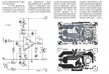
mi sono costruito l'amplificatore di elektor di cui allego lo schema.
però non funziona, all'aumentare dell'intensita del segnale scalda enormemente, inoltre non esce nessun segnale amplificato.
ho disaccoppiato la massa del segnale con quella di potenza con una resistenza da 2,8 ohm ed il difetto di scaldare è sparito, pero non esce nessun segnale amplificato.
ho anche aggiunto R6/C6 2,8 ohm/0,1 mf ma non esce nessun segnale.
a questo punto chiedo se qualcuno lo ha realizzato come da schema di elektor e se il suo funziona?
inoltre mi potete indicare uno schema funzionante fatto con due lm3886 a ponte?
lo schema che fornisce la TI è applicabile cosi come loro dichiarano oppure deve essere modificato.
grazie a tutti coloro che mi vorranno aiutare .
dimenticavo di chiedere se qualcuno conosce i moduli della Sanyo STK404-140 e se lo stampato ed anche il circuito eletrico sono affidabili, in quanto ho visto tesi di laurea dell'università di Padova in cui la serie STK viene citata nella tesi.
Guido Bullo
Hello everyone.
I built the elektor amplifier and attaching the scheme.
But it does not work, increase the intensity of the signal heats enormously, also does not leave any amplified signal.
I decoupled the mass of the signal with that of power with a 2.8 ohm resistor and the defect of heat has disappeared, but does not come out no amplified signal.
I added R6 / C6 2.8 ohm / 0.1 mf but does not come out no signal.
at this point I ask if anyone has realized as the elektor schema and if its working?
You can also specify a working diagram made with two LM3886 bridge?
the pattern that provides the TI is applicable as well as their state or be modified.
thanks to all those who want to help me.
I forgot to ask if anyone knows the modules of the Sanyo STK404-140 and if the printout and also the electrical network are reliable, because I saw the university thesis of Padua where the STK series is cited in the thesis.
Guido Bullo
Attachments
They are currently not able to provide images.
however, I created him as elektor pcb, are years that I produce printed circuit boards.
I replaced a second time all the parts but things do not change.
It is not the first time that the elektor projects do not work.
at the time when it was translated into Italian for the KIT distributor in Italy he said that certain progeti not work and therefore did not produce them.
Some also have built them too and did not work, to my regret I found what I was told.
Hello and thanks
Look up the LM3886 datasheet and use the circuit of that.
Yes - do this. I've used it with great success.
The only problems I can think of off the top of my head are incorrect PCB layout or switched power supply rails. I assume the chip is on a heatsink when you turn it on?
Hi,
I am using the same schematic with the exemption that I used only one resistor of 22k. In the schematic it showed 2x 22k resistors in series. For a test just remove one of the 22k resistor. It is possible that it is in mute. The switch must be closed to un mute the amplifier.
I am using the same schematic with the exemption that I used only one resistor of 22k. In the schematic it showed 2x 22k resistors in series. For a test just remove one of the 22k resistor. It is possible that it is in mute. The switch must be closed to un mute the amplifier.
arrived at this point I can only think that LM3886 is defective.
I have not mounted any resistance to the mute, because I do not care, maybe this is the mistake?
the chip is mounted on an oversized heat sink for use, the feeding and proper, at this point what remains to be done.
the PCB and the same as what I put in and all the tracks are perfect.
There has never happened that LM3886 is defective?
the components were purchased by me from RS Component Italy, someone can tell me if you have experienced unpleasant episodes with them?
thank you all
Guido
Hi,
If you do not install the resistor for the mute the chip will not play music. It is a most that you have the resistors installed.
If you do not install the resistor for the mute the chip will not play music. It is a most that you have the resistors installed.
"Mute resistance set up to allow 0.5 mA to be drawn from pin 8 to turn the muting function off."
RM = (|VEE| − 2.6V)/I8 where I8 > 0.5 mA
32.4/0.5 = 64.8kOhm
So RM must be less than 64.8kOhm, so 44kOhm should be fine. Just make sure the switch is closed (as has been said), else you'll be muting it.
I really hope you don't have a defective LM3886. I don't know about them being fake though. But here's a discussion: DIYAudio: LM3886 fakes??
mute?
basically I just have to insert the two resistances, closing the circuit, so that the project functions.
I can leave intact the values or you have to replace them.
thank you all.
Guido
basically I just have to insert the two resistances, closing the circuit, so that the project functions.
I can leave intact the values or you have to replace them.
thank you all.
Guido
basically I just have to insert the two resistances, closing the circuit, so that the project functions.
I can leave intact the values or you have to replace them.
thank you all.
Guido
Insert the resistors, close the connection, and just leave the values as they are.
basically I also feed LME49830, or I can do without it?
if I understand this is not a mute, but a secondary power supply for the chip.
thank you so much Mrcolc
Guido
if I understand this is not a mute, but a secondary power supply for the chip.
thank you so much Mrcolc
Guido
thank Mfcloc, works perfectly.
again I ask you to tell me if LME49830 must be supplied with the mute.
thank you very much
Guido
again I ask you to tell me if LME49830 must be supplied with the mute.
thank you very much
Guido
It looks like the mute on the lme49830 works in the same way. But the current is different. If you supply too much too the mute pin, you'll damage the chip.
It's close enough to say the resistor from Vcc to mute pin can be calculated:
Rm = (Vcc/0.16) kilo ohms
So if you have Vcc = 35V, Rm is 220k ohm.
I would say
for Vcc > 35V, use 220k
for Vcc < 35V, use 100k
You could also safely use 100k for any Vcc.
Remember, if you plan to use the mute, you need a 47 - 100 uF capacitor over Rm, and the switch must be switched to ground to mute. Apparently this is the ideal.
I only know all this because it's in the data sheet: LME49830
🙂
pretty much just food mute !!!!!!!!!!!!!!!!!!!!
I was making the same mistake I did with LM3886.
again many thanks to all.
Guido
I was making the same mistake I did with LM3886.
again many thanks to all.
Guido
- Status
- Not open for further replies.
- Home
- Amplifiers
- Solid State
- schematic for LM3886