
Re: Poor Mikeks, my old friend already read all electronics books
me too...old chap...me too....
destroyer X said:........worried about your future destiny..
Carlos
me too...old chap...me too....
Hi mikeks,
thanks for posting those PDFs, makes for interesting reading.
I'm wondering if anyone can explain this:
On page 2 of the first PDF, Derek Scotland states that TAG, quite rightly for a large production item, aims for repeatability of amplifier performance without the use of trimming components or the requirement for matching of components. Then, on page 7 - 8, he talks about precise compensation of semiconductor poles. Surely these two aims fly in the face of one another? The poles introduced by the various transistors in the circuit will surely not always be at the same frequency (from one amplifier sample to the next)? They are dependant upon device parasitic components, which vary from sample to sample, and some of which vary with signal level. It is quite possible that the forward poles of the amplifier are not even stationary, but move around slightly depending on the output signal.
HarryDymond said:I'm wondering if anyone can explain this.........
It mostly marketing blab really....

....up to the reader to sort the wheat from the chaff. 🙂
Hi
I have aquired another 8000a with a fault on the left output. It is the original mk1 with the 180 degree 5 pin din out/ins. The output transistors are short circuit on the left channel causing the 2a fuse to blow. I have removed these transistors which are BD912 and BD911's, and will problably end up blanket changing all of the other transistors associated with the left channel. Does anyone have any experience of repairing this version and if so could you share your knowledge with me. Also does anyone have a circuit diagram of this output configuration.
Thanks
Dave
Sorry friends
The circuit diagram within the thread is near enough perfect. I was not paying enough attention.
I now have quite a selection of short circuit or high resistence transistors and a coupe of discoloured resistors for my collection.
Any help would be appreciated.
Thanks
Dave
The circuit diagram within the thread is near enough perfect. I was not paying enough attention.
I now have quite a selection of short circuit or high resistence transistors and a coupe of discoloured resistors for my collection.
Any help would be appreciated.
Thanks
Dave
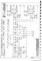
schematics diagram Audiolab 8000A
Hi, i 'm looking for the complete Schematics Diagram for
the Audiolab 8000A and if is it possible the Service Manual of it!!!
My ampli serial number is s/n:8942197.
Thanks of all!!!
Simon
Hi, i 'm looking for the complete Schematics Diagram for
the Audiolab 8000A and if is it possible the Service Manual of it!!!
My ampli serial number is s/n:8942197.
Thanks of all!!!
Simon

Audiolab 8000 LTSpice
I sat down for a little spice session and I keyed in a version of this amplifier. All of the spice models are available from the mfgr's web sites, easy to get if you don't have 'em already.
I guess the circuit is "love it" or "hate it". I like it, good to learn and study from. Never heard it, probably never will. Enjoy!
8000.txt rename to 8000.asc then view with LTSpice.
BTW, there are a few extra transistors on the output section, I think Audiolab left them out by mistake way back in '84 🙄.
Attachments
- Status
- Not open for further replies.
- Home
- Amplifiers
- Solid State
- Schematic for Audiolab 8000a