Hi,
My friend gave me a faulty Audiolab 8000a amp and I want to fix it. Is there anyone like to share?
Many thanks in advance
regards,
Edlo
My friend gave me a faulty Audiolab 8000a amp and I want to fix it. Is there anyone like to share?
Many thanks in advance
regards,
Edlo
Hi
I too would be interested in obtaing copy of an 8000a service manual. Also does anyone know where I would be a ble to source a power on off swith for this amp.
Thanks
Dave
I too would be interested in obtaing copy of an 8000a service manual. Also does anyone know where I would be a ble to source a power on off swith for this amp.
Thanks
Dave
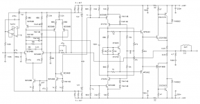
The circuit above looks OK. I have an old scan (very bad quality) of the Cambridge Audiolab 8000A (dated 1984) and it is almost the same. Difference is that my scan shows a Vbe multiplier with only one NPN transistor instead of the two transistors (NPN + PNP) in the circuit above.
Another difference is that in my scan the feedback is taken after the output relay. The relay is double throw (loudspeaker and headphone selection I assume), the 2k7//47p for feedback is used twice, once form the loudspeaker connection, once from the headphone connection. The servo is connected right at the 0.22 output resistors, just as in the circuit above.
My scan is too big and too bad quality to attach.
Steven
Hi
than you for you replies, there are slight differences from the circuit posted but on the whole it is quite accurate. All I need to source now is the power on off switch.
Once again thanks
Dave
than you for you replies, there are slight differences from the circuit posted but on the whole it is quite accurate. All I need to source now is the power on off switch.
Once again thanks
Dave
Hi,
that schematic has some really nice details, no miller comp, cascodes, LTP compensation , DC servo, low voltage input stage, properly scaled Thiel network, etc.
However can someone explain the circuit from second LTP to VAS (cascoded). There appears to be voltage gain here as well as Hi freq comp for the LTP. The 3k9 is the load for the LTP. The second LTP seems to have no method of balancing collector currents.
What do the 3 diodes in the collectors of the first LTP do?
Thoughts please.
Yes, second LTP has gain, emitter resistor 680 Ohm, collector resistor 3k9. Freq. comp. is also there.
Collector currents of second LTP are balanced because the gain from both collector outputs is the same. They are both loaded with 3k9 to the VAS. The gain of the VAS is determined by the 47k load resistors; the same for positive and negative half. The overall feedback takes care now of properly balancing the currents in the second LTP.
The 3 diodes in the first LTP are for clamping in case of overload. It is a Baker clamp. The BC556 in the current mirror of the first LTP cannot saturate bacause 2 diodes take care that the Vce is at least one diode drop (Vbe). Going from top to bottom along the 4 diodes: the first one is part of the mirror, the second and third are the Baker clamp against overload in one direction, the fourth one is against overload in the other direction. This avoids that the second LTP gets reverse biased.
Steven
Brilliant stuff. Always been intrigued what was under the lid of these amps. Looks like it lives up to the hopes!
richie00boy said:Looks like it lives up to the hopes!
Not sure i agree....different strokes for different folk i suppose....

despite the Brochure Babble.. The Audiolabs in question were decent amps.. but not nearly as good as the Sales brochure intimated they would be... this was reflected in the Marketplace.
The output stage looks promising....but requires at least thre pairs of output devices....
....the rest of the design is slavishly based on Otala's philosophy...which is inherently flawed.....
For instance, there is no earthly reason why foward-path bandwidth should exceed the nominal audio bandwidth.....
Additionally, triple gain-stage designs are only useful in the context of a nested feedbak/feedfoward compensated design.....
Hello.
Mikeks.
Why the Otala's philosophy amplifier is inherently flawed...?
Thank.
Guillermo Eirín
Mikeks.
Why the Otala's philosophy amplifier is inherently flawed...?
Thank.
Guillermo Eirín
Hi,
I had a look at the TAG Maclaren article and compared their diagrams to the old Audiolab 8000a schematic recently posted.
Only 2 differences;- the DC servo is now non-inverting and Fet input.
Everything else appears identical.
No wonder then that Tag have decided to revert back to the Audiolab name, they appear unable to improve the design of their branded version.
I would like to see the latest generation of Audiolab amplifiers and the final generation of 8000 (M or P) series before the Tag takeover. It may give some insight into their continuing development and fine tuning.
Hi there People
I would be very interested in any other schematics for the 8000 series. Especialy the Q as I can see there is space for balanced outputs. Perhaps a diy route........
dave
I would be very interested in any other schematics for the 8000 series. Especialy the Q as I can see there is space for balanced outputs. Perhaps a diy route........
dave
Poor Mikeks, my old friend already read all electronics books
And now returning to more basic things.... well, this is good to me, to increase my knowledge, but may be very boering to you.
As you understand of natural philosophie, as Gluteus Maximus, great scientist that one, use to show us how deep is the reality Mikeks, i am sending you regards and worried about your future destiny.
Wonderfull girl in that picture, in special if you have that beauty surrounding you...must be a "conaisseur" to give the real value to that wonderfull "brownie"
ahahaha...philosophie was wonderfull!...and you and SY can capture fast that.
regards,
Carlos
- Status
- Not open for further replies.
- Home
- Amplifiers
- Solid State
- Schematic for Audiolab 8000a