Long story short, rats made a home in my trunk via the breathing vents and the rain flooded my trunk.
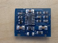
But with the help of this forum, Perry's Basic Car audio site and barevids amp repair youtube channel, I managed to repair my audison SR4 amp without replacing everything, but messed up on my SR1DK. After repairing the power supply section, I traced the issue to the AD2K module. I tried to remove the module and the legs decided to pull itself away from the board. So I decided to remove the components to repair or maybe rebuild the board. After removing an optocoupler, more traces decide to detach itself.
I'm wondering if anyone has a schematic for this audison AD2K module or/and the output section for this amp, before I painfully trace the board with my poor vision
The main circuit board is a SR1DK rev.E
Thanks!
Attachments
Hello. I am also looking for an AD2K circuit diagram. I bought a damaged audison srx 1d for repair. Unfortunately, the AD2K board is missing. Does anyone have a schematic of this board, or accurate photos without integrated circuits
Thanks in advance.
Thanks in advance.
If you can't buy one from the manufacturer, try to find a warranty or authorized repair shop to buy one from.
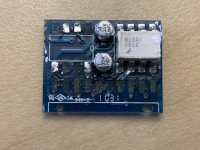
Thank you for your interest. I searched but not available. I will easily make such a circuit board, but I must have a diagram or photo of the circuit board. The image must be without a comparator and optocouplers for the paths to be visible.
The pictures above are almost good, only the LM219 and FOD3180 cover the paths.
Of course, the best would be the diagram ...
pho604 do you still have this AD2K module ???
The pictures above are almost good, only the LM219 and FOD3180 cover the paths.
Of course, the best would be the diagram ...
pho604 do you still have this AD2K module ???
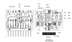
Hello. I had some time and I did pcb. I connected everything and the amplifier works, but I haven't tested at full power yet, because the amplifier is not mounted on cooling.
I have a nice square wave on mosfets, but I am worried about the frequency, it is 218kHz. In my opinion too high.
Does anyone know what the frequency should be there ???
Thank you and best regards
I have a nice square wave on mosfets, but I am worried about the frequency, it is 218kHz. In my opinion too high.
Does anyone know what the frequency should be there ???
Thank you and best regards
If this is a self-oscillating class D, the idle frequency will be higher than when driving high power. If this amp is designed for higher than sub frequencies, they may use higher than normal frequencies.
I understand, but I made the control board myself and would like to know the frequency on the original pcb from the factory. I'm afraid I made a mistake. I have already measured a lot of D class and it has never been so high.
If anyone knows or can measure I will be grateful.
Regards.
If anyone knows or can measure I will be grateful.
Regards.
Why not put it in the heatsink and drive it into a load to see if it drops down to what you expect?
If you used the correct values, especially in the feedback loop (assuming that it's self oscillating), it's likely normal.
You can wait for someone but the wait could be from seconds to days or never.
If you used the correct values, especially in the feedback loop (assuming that it's self oscillating), it's likely normal.
You can wait for someone but the wait could be from seconds to days or never.
- Home
- General Interest
- Car Audio
- schematic for an audison AD2K module?