Would not be my first or ever choice.. 
Might consider the SV83, but honestly I don't believe in designing things based on what I have on hand unless it is both insanely expensive and perfectly suited to the task. Your choice of driver tube is going to determine to a large extent how well this thing is going to work, and is a tiny % of the overall cost of the project - why hobble it at the onset?
No interest in a thread name change?
6688 is readily available on eBay and would be a good choice.
Thread retitled as discussed..

Shoog
Ok, so I'm going to use 6688 as a preamp tube. I understand how load lines work for triodes and there are many examples of how to use them. Pentodes? Not so much. But in just looking at the graph it seems that current doesn't change much with increased voltage. And the curved area is a very small percentage of the load line.
It seems the 'knee' of the curve is about 25 volts anywhere between 6 and 16 ma? So the real question is how much current would be needed to drive a 6550 with this tube?
It seems the 'knee' of the curve is about 25 volts anywhere between 6 and 16 ma? So the real question is how much current would be needed to drive a 6550 with this tube?
Last edited:
Its not very empirical, but run the 6688 at the maximum standing current which will ensure longest life. From the datasheet that suggests about 10mA at B+ 180V g2 at 150V.
The point is that the more Schade applied the harder it becomes to drive and this especially applies to driving input capacitances. So in absolute terms you would have to design the circuit before you could answer the question - how much driver current ?
Can I suggest that you try reading the Tubecad article in an attempt to understand the internal dynmaics of what is going on. Its a tough read - but really is the only explanation which really goes into detail as to the relationship between the driver and the output. Be warned, I had to read it a few times before I started to glean what was going on.
http://www.tubecad.com/march2001/
Shoog
Last edited:
Hey All,
I haven't forgotten this thread. I was learning how to work Lt spice. At least well enough to get this far. Special thanks go out to Kevin KR for all his help!
I would appreciate any suggestions on how to improve the amp, especially at clipping, if that is possible.
Also, any suggestions for the .22uf input cap and the .22 coupling cap. I need to know the best type of input cap and a voltage for it.
As always thanks for all the great input.
Attachments
Last edited:
Some questions and comment:
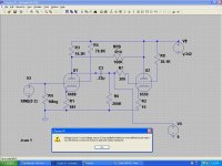
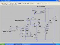
- what is the purpose of V1?
- why isn't U1's screen bypassed?
- how do you overdrive 6688 with 0.231V?
- try a longer time span for .tran to make sure the circuit has settled down, and shorten the time step to 1u (it should reduce the slope on the FFT somewhat).
- what is the purpose of V1?
- why isn't U1's screen bypassed?
- how do you overdrive 6688 with 0.231V?
- try a longer time span for .tran to make sure the circuit has settled down, and shorten the time step to 1u (it should reduce the slope on the FFT somewhat).
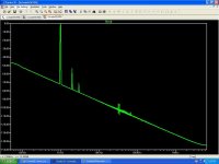
LTspice sets 0dB as 1V rms, so the first graph showing 0dB into 8 ohms represents 125mW. The second, which looks to me to be about +15dB which is close to 4watts. This represents about 6.62 volts. The transformer ratio is close to 19:1 so the plate signal will be about 105V rms or 300V peak to peak. With a 362V supply that's about as good as you will get.
Cheers
Ian
Cheers
Ian
The datasheet suggests that you could get 12W out using a plate load of 1K5. Your choice of plate load is more appropriate for a higher voltage of 400V and g2 of 250V.
http://www.dougstubes.com/6550-tungsol.pdf
Shoog
http://www.dougstubes.com/6550-tungsol.pdf
Shoog
More LT Runs
Hey All,
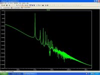
Had a second day off today. Spent an hour outside the UPS guard shack this morning. But I finally wrested my new LCR meter away from them. And ran the simulations with the correct transformer inductance specs. See attached FFTs.
V1 is a positive bias for the 6688. With it the tube draws 14.8ma. Set the voltage to zero and it draws 6.5ma. (positive bias was Kevin's idea.) Tried bypasing the grid. Bad Joo joo. When I did the top of the wave form became perfectly round. Starting to clip? Used 10uf to 100uf and it only got worse. Without it I have a perfect waveform.
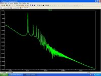
The correct transformer specs resulted in all that distortion in the higher frequencies at 1.5 watts. Is that distortion going to be audible?
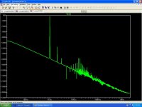
Left is 18 watts, right 1.5 watts
Hey All,
Had a second day off today. Spent an hour outside the UPS guard shack this morning. But I finally wrested my new LCR meter away from them. And ran the simulations with the correct transformer inductance specs. See attached FFTs.
V1 is a positive bias for the 6688. With it the tube draws 14.8ma. Set the voltage to zero and it draws 6.5ma. (positive bias was Kevin's idea.) Tried bypasing the grid. Bad Joo joo. When I did the top of the wave form became perfectly round. Starting to clip? Used 10uf to 100uf and it only got worse. Without it I have a perfect waveform.
The correct transformer specs resulted in all that distortion in the higher frequencies at 1.5 watts. Is that distortion going to be audible?
Left is 18 watts, right 1.5 watts
Attachments
Last edited:
Indutance
A general question? The attached FFT is at about 1 watt. Much cleaner than with the correct values. The only difference was that the inductance that I guessed at was about twice the inductance of the actual transformer. Is there a way to increase inductance without changing the other specs of the transformer?
A general question? The attached FFT is at about 1 watt. Much cleaner than with the correct values. The only difference was that the inductance that I guessed at was about twice the inductance of the actual transformer. Is there a way to increase inductance without changing the other specs of the transformer?
Attachments

A general question? The attached FFT is at about 1 watt. Much cleaner than with the correct values. The only difference was that the inductance that I guessed at was about twice the inductance of the actual transformer. Is there a way to increase inductance without changing the other specs of the transformer?
If you are asking if you can keep the same winding ratio but with larger primary inductance, then yes, simply double both the primary and the secondary inductance in your example above.
- Status
- This old topic is closed. If you want to reopen this topic, contact a moderator using the "Report Post" button.
- Home
- Amplifiers
- Tubes / Valves
- Schade SE 6550