This is going to be a design & build thread of a project I am currently undertaking which involves the use of The following drivers in a 3 way stereo loudspeaker setup:
Scanspeak D2905/95000 Tweeter
Morel EM 428 Midrange
2x Scanspeak 18w/4531G00 Lower Mid/Bass
I have designed the cabinets using 3D software and had them machined by Wilmslow audio as can be seen in the attached pictures. I am currently in the process of building these.
The crossovers have been simulated from the driver manufacturers data using the FRD Consortium tools, including unibox, baffle diffraction simulator and the frequency response combiner to account for baffle step etc. The crossover simulation is attached below. The crossovers are currently being built (pictures to follow).
I am looking to obtain measuring equipment upon completion of the build to determine the accuracy of the simulation and carry out any necessary tweaks to the crossovers.
Cabinet Drawings:
https://www.dropbox.com/s/8nzwrfb6cbutts1/Speaker Cabinet Drawings AFC.pdf?dl=0
Cabinet Renders:


Cabinets so far


Crossover Simulation


Scanspeak D2905/95000 Tweeter
Morel EM 428 Midrange
2x Scanspeak 18w/4531G00 Lower Mid/Bass
I have designed the cabinets using 3D software and had them machined by Wilmslow audio as can be seen in the attached pictures. I am currently in the process of building these.
The crossovers have been simulated from the driver manufacturers data using the FRD Consortium tools, including unibox, baffle diffraction simulator and the frequency response combiner to account for baffle step etc. The crossover simulation is attached below. The crossovers are currently being built (pictures to follow).
I am looking to obtain measuring equipment upon completion of the build to determine the accuracy of the simulation and carry out any necessary tweaks to the crossovers.
Cabinet Drawings:
https://www.dropbox.com/s/8nzwrfb6cbutts1/Speaker Cabinet Drawings AFC.pdf?dl=0
Cabinet Renders:
Cabinets so far
Crossover Simulation
Hello Andrew
Some might suggest; the Scan Bass L will have lobing issues with the Morel.
You can go with a 3.5 way to alleviate this.
May I suggest a 4-way.
May I suggest tuning your new Scan Bass L port to an Fs below 33Hz. You will need to close off the holes in the support braces. We need a separation of drivers. The output from the port will now sum in phase with the Bass U and L. The Scanspeak has x-max of +/- 6.5mm, and an x-mech of +/- 11mm. Nice.
May I suggest my transient perfect, phase stable, impedance stable fully balanced dual cascade paralleled series crossover?
Attached is the schematic.
Always attach the woofers first. The circuit degausses the drivers. You will hear a light thump. This is the basket demagnetizing.
PLEASE, listen to YOUR simulated crossover first. Then listen to mine.
Not in your wildest dreams. Vocals are to die for. Drums have the attach of a live performance. Transient Perfect.
Attachments

Hello Andrew
Some might suggest; the Scan Bass L will have lobing issues with the Morel.
You can go with a 3.5 way to alleviate this.
May I suggest a 4-way.
May I suggest tuning your new Scan Bass L port to an Fs below 33Hz. You will need to close off the holes in the support braces. We need a separation of drivers. The output from the port will now sum in phase with the Bass U and L. The Scanspeak has x-max of +/- 6.5mm, and an x-mech of +/- 11mm. Nice.
May I suggest my transient perfect, phase stable, impedance stable fully balanced dual cascade paralleled series crossover?
Attached is the schematic.
Always attach the woofers first. The circuit degausses the drivers. You will hear a light thump. This is the basket demagnetizing.
PLEASE, listen to YOUR simulated crossover first. Then listen to mine.
Not in your wildest dreams. Vocals are to die for. Drums have the attach of a live performance. Transient Perfect.
There is no reason to go 3.5-way in this setup, unless to improve BSC issues. The lambda of distance at xover of 500 Hz is 27", and he appears to be about 18" offset from mid to lower woofer. He is well within the lobing standard criteria.
Sure- the electrical phase would be akin to a diaural circuit since everything is on both sides, but that really isn't necessary. When you have AC and series components, both current flows will see the same series components.I don't see how the acoustic phases would be well aligned here though. You can't account for offset of the acoustic centers by using textbook formulae, which I'm assuming you used since all xover component values at junction are the same between drivers.
The baskets are aluminum on the Revelators- which means they can't be magnetized.
To the OP- the impedance shows a sealed box alignment. The peak at 1.5k could pose some fatigue issues, and the 2.5k peak can likely be reduced by applying a 0.22uF cap across the 0.85mH coil. The acoustic phases really could track a bit better with component adjustments.
Nice start to a great project!
Wolf
May I suggest my transient perfect, phase stable, impedance
stable fully balanced dual cascade paralleled series crossover?
Hi,
May I suggest you get a good technical grounding
before spouting such utter technical nonsense.
Its pseudotechobabble at its utter worst.
rgds, sreten.
Last edited:
Interesting circuit. When I model it, assuming ideal 8 ohm drivers, I get the attached response. Something wrong with the midrange component values?Attached is the schematic.
Attachments

I would stick with your simulation and tweak from there.Interesting circuit. When I model it, assuming ideal 8 ohm drivers, I get the attached response. Something wrong with the midrange component values?
I wasn't planning on taking this any further. I was just interested in seeing how the network worked. It looks like some of the values given in post #2 may be incorrect. What are the intended transfer functions to each of the drivers? I am curious to know how the component values are determined when there is a lot of interaction between the sections. I expect that calculating them analytically might be quite complicated.
This is a brand new crossover idea.
It is being developed on a different thread. sreten is one of my biggest supporters.
There is no simulation software for it.
system7 came up with some crossover values. He pointed out this is a variation of 'Bud Frieds' ideas.
Attached is the near field measurement of my 4 drivers.
It is being developed on a different thread. sreten is one of my biggest supporters.
There is no simulation software for it.
system7 came up with some crossover values. He pointed out this is a variation of 'Bud Frieds' ideas.
Attached is the near field measurement of my 4 drivers.
Attachments

Drivers aren't constant 8 ohm load, and don' have perfectly flat FR and all the same sensitivity. I expect the OP used simulated on-the-baffle FR (he stated that he used FRD consortium tools).Interesting circuit. When I model it, assuming ideal 8 ohm drivers, I get the attached response. Something wrong with the midrange component values?
My only suggestion for the crossover is to lower the mid (1-2 dB), and also the tweeter (2-3 dB), a slightly tilted response could work better. It could be only a question of different resistors, so cheap enough for a try.
Ralf
Drivers aren't constant 8 ohm load, and don' have perfectly flat FR and all the same sensitivity. I expect the OP used simulated on-the-baffle FR (he stated that he used FRD consortium tools).
My only suggestion for the crossover is to lower the mid (1-2 dB), and also the tweeter (2-3 dB), a slightly tilted response could work better. It could be only a question of different resistors, so cheap enough for a try.
Ralf
shc was not modeling the OP's xover. He was modeling Cousin Billy's xover. With what CB posted for FR plots, I can see that shc's result is likely not too far off. Even if they were to reduce the lower mid's magnitude, the upper mid still does not rolloff; and there is no combined FR, impedance, or phase response to look at. Besides the original driver measurements, it's a shot in the dark.
CB- I don't think it's anything 'new' in terms of circuit/xover. I can say the reasons for your peaking in the FR is likely that there is no 'spread' for the 1st/2nd order diaural xover to sum at the same level as the nominal plot. The response should sum at reference, and each response be -6dB at the xover point between drivers. However- your circuit does not take any resonances or energy storage issues into account, let alone Q of the filter to conjoin at -6dB.
In short- it needs some work.
Later,
Wolf
This is a brand new crossover idea.
It is being developed on a different thread.
sreten is one of my biggest supporters.
There is no simulation software for it.
Hi,
I wouldn't put it quite like that. Your claiming its the
greatest crossover design ever, I'm claiming you
have no idea what you are really talking about.
The same goes for B.F.'s nonsense musings.
rgds, sreten.
wolf_teeth
Thank you, my new friend.
Diaural
I just 'searched' DiAural circuit. Kimber Kable's claims on what the circuit does mirror my own.
Apparently the diaural circuit expands on series crossover theory from 50-60 years ago.
sreten, Mr. Kimber called it the greatest crossover as well. I'm not the only one.
My fault.shc was not modeling the OP's xover. He was modeling Cousin Billy's xover.
Still my suggestion for a slightly tilted FR is valid. I find a flat FR too bright.
Ralf
I just 'searched' DiAural circuit. Kimber Kable's claims on what the circuit does mirror my own.
Apparently the diaural circuit expands on series crossover theory from 50-60 years ago.
sreten, Mr. Kimber called it the greatest crossover as well. I'm not the only one.
Hi,
Self indulgent pseudotechobabble, like the DiAural and
B.F.'s musings mean absolutely squat in any real terms.
Simple fact is, you don't know what you are doing, and
engaging in very pointless egoistic self aggrandisation.
rgds, sreten.
Last edited:
Wolf - Thanks for your feedback. I will try some tweaking to bring the phase of the drivers closer together although I have been having difficulty achieving this so far. As it stands they track moderately well around the crossover points and I have been having difficulty to get them closer over a broader frequency without adversely affecting FR. Any advice you may have here would be appreciated for future tweaking. Currently, if i reverse the polarity of the tweeter, I do get a large dip to 50dB just fyi.
I have played around a bit with adding a capacitor in parallel with the 0.85mH inductor (in my simulation) which did reduce the peak at 2.5khz as you suggested so thanks for the tip.
FYI I have modeled the measuring point @ 1m from the tweeter, allowing for acoustic centres as best as I could predict using trig and diver offset on baffle (as per Driver Offset Calculator). This method alters the apparent phase of the drivers at the measuring point.
The first peak at 1.5k is just the respnse of the driver (according to my FR data as processed with the FRD tools) so I will have to live with it. It is also shown on the raw FR data from the manufacturers PDF file.
Giralfino - Thanks as well, with regard to reducing tweeter+mid volume, I have thought this also and will look to tweak the L-pads to allow for a slightly sloped overall response and compare with and without once I have built them.
Thanks all,
Andy.
Last edited:
Wolf - also forgot to mention, with regard to the bass speakers impedance plot representing a closed box, this is because I was unsure how to use the modified impedance in unibox and combine it with the impedance&phase output in a similar way in which I combined the baffle step & box calcs into the FR using the frequency response combiner from the FRD consortium.
My thoughts on this were it should not impact the design too much as the upper section of the impedance plot for the drivers should be mostly unaffected - although please correct me if I'm wrong in this assumption.
My thoughts on this were it should not impact the design too much as the upper section of the impedance plot for the drivers should be mostly unaffected - although please correct me if I'm wrong in this assumption.
Andrew- does the reverse null look as good when you reverse the polarity on the midrange only? This will show you the overall alignment rather than just 2/3 of it.
Another thing worth mentioning is that zobels aren't really always warranted. Sometimes they can tilt the response downward to a detriment, even if the impedance looks better as a result.
The phase can be dialed in by adding small resistances to the shunt-legs of the components, say 1-3 ohms, but this also will shift your response curve. If that does not help, you can likely do better by going one full xover order difference electrically between drivers. In your 3-way, it would (elec) be 12dB LP on woofer, 3rd HP on mid, 2nd LP on mid, 3rd HP on tweeter. The extra phase shift helps align the acoustic centers on a flat baffle design. This is why an LR4 acoustic on a 7" 2-way is typically 2nd/3rd asymmetric electrically. BTW- it is usually better to have the higher freq driver to be the higher order in terms of transient response and impulse, but 1-order shift either way will improve phase alignment on a flat-baffle design.
Also of note-
-Your breakup on the woofers is suppressed sufficiently.
-You might be able to get a little more bandwidth out of the mid xovering at 400Hz ish. This may actually reduce the peaking in the FR resulting from bandpass gain. Maybe just a bit more midrange attenuation will tame the peak in reality.
-Using a split L-pad will result in less electrical phase shift. Series resistor before the xover circuit, and parallel resistor after. You don't have bad electrical phase, but this can help if fixing other things makes this worse.
-I don't find your mid to woofer acoustic phase all that badly aligned, but the tweeter to mid doesn't look that great. I would try going 3rd order on the tweeter. In the response, the peak at 2.5k is caused by the breakup of the midrange, and the higher magnitude of the tweeter. Tweeter 3rd order may improve the peak as well as the notch I previously recommended.
-I know you likely made the woofers in series to provide an 8 ohm final load. In reality, this makes the woofer xover harder. You need more coil to provide the rolloff, which also can induce a peak in the FR at resonance of the woofer, and the inductance of the woofer setup is twice that of a single as opposed to half like a parallel pair would be. You don't have to have the same impedance in all areas of the design, just in case you didn't know that.
Ask if you have any more Q's,
Wolf
Scanspeak D2905/95000 Tweeter
Morel EM 428 Midrange
2x Scanspeak 18w/4531G00 Lower Mid/Bass
You seem to connect the two 4531G in series, probably to avoid the low impedance dip from two parallel 4-Ohm drivers. However, with a series connection, the two drivers will not see the same voltage across their terminals if they are not perfectly matched. This may be very difficult to control in our voltage driven world (things would be different with current drive, but that's a rare thing).
I'd suggest to use the two 8531G (8-Ohm variant) in parallel to avoid this issue.
Wolf - Thanks for the advice. I will continue to play around with my simulation taking into account your suggestions and see how I get on (I may also ditch the Zobels). Once my original crossover components arrive and I have setup some measuring equipment, I'm going to measure the response of the drivers in the baffle and also with my initial x-over config to see how closely the simulation FR matches reality then go from there.
mbrennwa - Thanks, I also realise this would be a better option, but I already own all of these drivers and materials, the woofers were from an older project from quite a few years ago so i decided to reuse them for this. I will just have to live with the 4ohm drivers in series and see how they get on in reality. In the past I have used series drivers before with good success and they didn't seem to pose as many problems as they might in theory. I cant use them in parallel as it leads to a very low impedance of around 2.5ohms for much of the lower end.
As an extra note, I have also figured out how to simulate the double impedance peak of the woofers in my reflex cabinet so I will incorporate this in my next simulations to see if it does influence the FR at all.
**Update**
Hi guys, slight delay with the update but here it is never the less...
I have now finished building the cabinets although I am yet to Veneer them and paint the baffles piano black. The project has taken a bit of a turn since my last post - I Have invested in a Mini DSP Umik1 calibrated microphone, spent lots of time getting used to taking indoor measurements with gating etc. and decided ultimately to go down the route of an active crossover, in the form of the Mini DSP DRC-DA8 which also acts as a DAC and this is hooked up to a 6 channel Power amp (Rotel 1506).
I decided to do this instead of a passive crossover for several reasons in the end, with the main ones being ease to experiment, tweak, efficiency and potentially better results although this is arguable.
I have so far used my simulated FRD files to build my active crossover as I have had difficulty getting accurate measurements for low frequencies due to room gain & nodes etc. I have used tweaked versions of LR 4th order IIR filters in combination with parametric equalisers to flatten the response of each drive on baffle individually. I have implemented delay to compensate for each drivers acoustic alignment to bring relative phase between the drivers as close as possible at the crossover points. I have also theoretically calculated the reflex port length based on my Unibox file used in the FRD simulation process, based on a 65L reflex cabinet using 2x 18w-4531g00 Drivers in series (I also accounted for the factor detailed in this excellent page Port Calculation).
I can confirm by ear the results are very pleasing so far and I feel like I am 90% of the way with regards to tweaking the crossover, although I intend to carry out measurement based tweaking soon once I get chance and measuring the final response outdoors once the weather starts to clear up a bit! I also intend to try FIR filtering at a later date to get a linear phase speaker - although for now my aim is to finalise the tweaking of the IIR filters already in place.
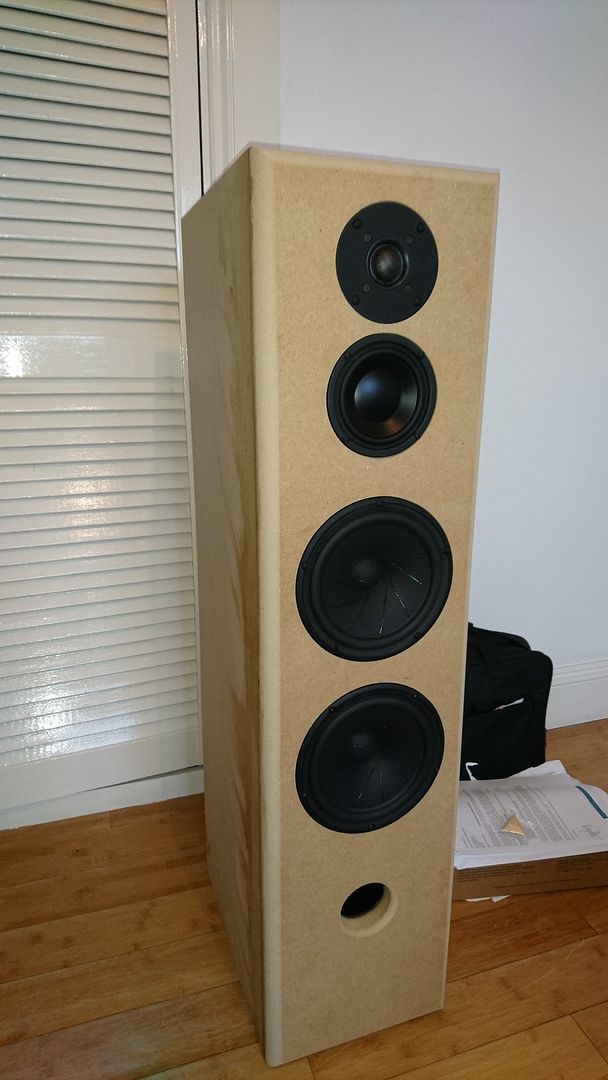
Speakers so far:
Simulated results below:
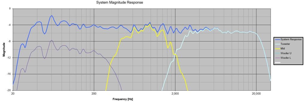
Overall FR:
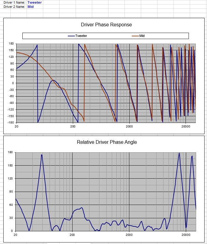
Phase Tracking Tweeter/Mid:
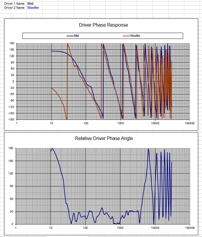
Phase Tracking Mid/Woofers:
(The phase is slightly more difficult to simulate properly here due to using 2x woofers at different vertical positions on the baffle altough combing does not seem to be an issue as they are crossed over quite low)
Hi guys, slight delay with the update but here it is never the less...
I have now finished building the cabinets although I am yet to Veneer them and paint the baffles piano black. The project has taken a bit of a turn since my last post - I Have invested in a Mini DSP Umik1 calibrated microphone, spent lots of time getting used to taking indoor measurements with gating etc. and decided ultimately to go down the route of an active crossover, in the form of the Mini DSP DRC-DA8 which also acts as a DAC and this is hooked up to a 6 channel Power amp (Rotel 1506).
I decided to do this instead of a passive crossover for several reasons in the end, with the main ones being ease to experiment, tweak, efficiency and potentially better results although this is arguable.
I have so far used my simulated FRD files to build my active crossover as I have had difficulty getting accurate measurements for low frequencies due to room gain & nodes etc. I have used tweaked versions of LR 4th order IIR filters in combination with parametric equalisers to flatten the response of each drive on baffle individually. I have implemented delay to compensate for each drivers acoustic alignment to bring relative phase between the drivers as close as possible at the crossover points. I have also theoretically calculated the reflex port length based on my Unibox file used in the FRD simulation process, based on a 65L reflex cabinet using 2x 18w-4531g00 Drivers in series (I also accounted for the factor detailed in this excellent page Port Calculation).
I can confirm by ear the results are very pleasing so far and I feel like I am 90% of the way with regards to tweaking the crossover, although I intend to carry out measurement based tweaking soon once I get chance and measuring the final response outdoors once the weather starts to clear up a bit! I also intend to try FIR filtering at a later date to get a linear phase speaker - although for now my aim is to finalise the tweaking of the IIR filters already in place.
Speakers so far:
Simulated results below:
Overall FR:
Phase Tracking Tweeter/Mid:
Phase Tracking Mid/Woofers:
(The phase is slightly more difficult to simulate properly here due to using 2x woofers at different vertical positions on the baffle altough combing does not seem to be an issue as they are crossed over quite low)
- Status
- Not open for further replies.
- Home
- Loudspeakers
- Multi-Way
- Scanspeak & Morel 3-Way