OPPSSSS
i was reading my post above and i noticed that i typed in the word 'regular'. i meant 'regulator'.
sorry, just a typo... no meanings intended.
i was reading my post above and i noticed that i typed in the word 'regular'. i meant 'regulator'.
sorry, just a typo... no meanings intended.
Hi Bob,
I got the stuff. Everything is there. I would like to thank you for your legwork and the great guide you wrote. I appreciate your efforts to educate me. I have a couple questions that may seem obvious but I have not built a power supply before.
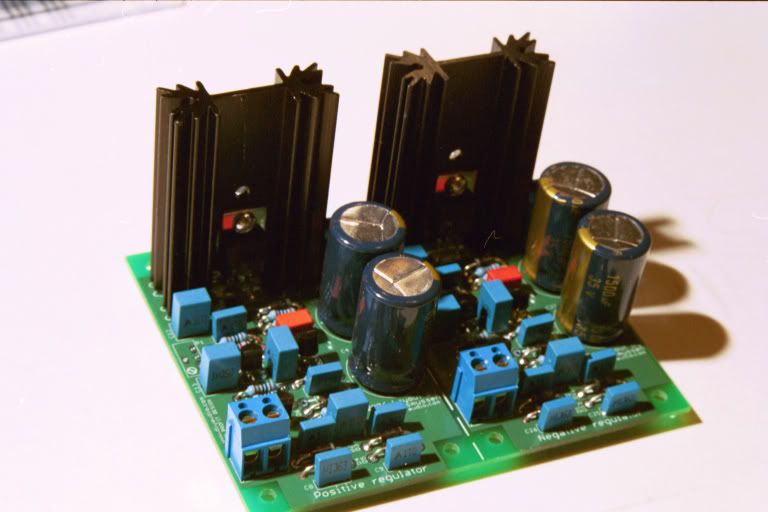
Are the heatsink pins meant to be soldered to the board or do you just attach the semicondutor to it?
I noticed that you omitted the diode at D8/D10. Is that an optional part?
What is the purpose of the LED? Could I mount that on the front panel as a power indicator? Maybe it is not even necessary.
Thanks, Mike
I got the stuff. Everything is there. I would like to thank you for your legwork and the great guide you wrote. I appreciate your efforts to educate me. I have a couple questions that may seem obvious but I have not built a power supply before.
Are the heatsink pins meant to be soldered to the board or do you just attach the semicondutor to it?
I noticed that you omitted the diode at D8/D10. Is that an optional part?
What is the purpose of the LED? Could I mount that on the front panel as a power indicator? Maybe it is not even necessary.
Thanks, Mike
Hi,
D8 & D10 are an alternative to D7 & D9.
The LED/R16 current + the R2/R11 current give a minimum draw on the active circuit. These loads may ensure stability.
Has anyone checked this yet?
You should be able to mount the LEDs anywhere as indicators.
D8 & D10 are an alternative to D7 & D9.
The LED/R16 current + the R2/R11 current give a minimum draw on the active circuit. These loads may ensure stability.
Has anyone checked this yet?
You should be able to mount the LEDs anywhere as indicators.
Apologies if this is too obvious or if I missed it somewhere in the thread, but how do I calculate the power dissipated in the MJE-transistors?
/U.
/U.
 Thanks!
 Hi Bobellis,
how many watts of dissipation would you expect from those tall sinks?
What maximum current would that equate to with either the 15Vac or 18Vac transformers?
how many watts of dissipation would you expect from those tall sinks?
What maximum current would that equate to with either the 15Vac or 18Vac transformers?
Hi Nisbeth,
that's not what I am asking.
Taking account of Tc and Rths-a, Rthc-s, what is Bob expecting as the dissipation?
that's not what I am asking.
Taking account of Tc and Rths-a, Rthc-s, what is Bob expecting as the dissipation?
The nutshell answer is that the 2" sinks should be good for 5W, assuming that there is some air circulation.
The 15V transformer gives about 20VDC, so 5 V dropped means 1A maximum. Note that this is also the MAXIMUM rating of the 1N4007, so either swap them out or derate a bit.
The derivation:
The MJE13032/33 Rth(j-c) is 2.5 per the datasheet.
Gengis' sinks are Aavid, rated at 7 C/W at 70ºC sink-air. Fischer rates at an unspecified lower s-a temp than Aavid, so we'll use that to start.
A generic Rth(case-sink) is .7 when mounting directly with just grease. But, there are these darned holes reducing the contact area. I'll use 1 as a fudge factor. So we have:
Rth(j-c) 2.5
Rth(c-s) ~ 1
Rth(s-a) 9
________________
Rth(tot) 12.5 ºC/W
For those wondering
Rth = R-theta
(j-c) = junction to case
(c-s) = case to sink
(s-a) = sink to air
(tot) = junction to air through sink
Assuming that you want to keep the junction temperature below 100ºC, starting with inside your case temperature of 35ºC, you have 65ºC of rise available. 65ºC / 12.5ºC/W = 5.2W and the sinks will be at ~46.8ºC above ambient, or 82ºC at 5.2W
Since we don't know the conditions of Fischer's ratings, let's use use Conrad's derating guide on their technical page to calculate Rth(s-a) based on Aavid's 70ºC rise data. Since Conrad rates their sinks at 80ºC above ambient, we look for the correction factor at 37ºC rise. This factor is 1.29, so multiplying this by Aavid's 7ºC/W, we get 9.03. (a familiar number).
The next part of verifying heat sink adequacy is to apply the device's derating factor. Since the case will be mounted on a 82ºC sink, and we must derate the devices by 0.4 W/ºC above 25ºC, the derating factor is 22.8W. Subtracting this from the devices rated 50W, we have plenty of operating area left.
You could dissipate more if you are willing to allow the junction temperature to rise above 100ºC. I just use 100ºC because Nelson Pass suggested it as a reasonable target for reliability. The rated maximum junction temperature is 150ºC, so allow yourself a bit of room. At 7.2W you'll have junction temperature of 125ºC and rated dissipation of 20W. Probably as close to the limit as you really want to go
Hi Bobellis,
thanks for that very comprehensive reply.
Taking a guess at the 18Vac transformer output of about 24Vdc gives a voltage drop of 9V.
Your 5.2W indicates 580mA continuous on a 24Vdc (18Vac) supply and 1A continuous for the 20Vdc (15Vac) supply.
Obviously these numbers increase for peak (short term) current duty.
Thanks again.
I'm on my way to the post office with US shipments. You should have received an email with the tracking number.
Bob, I did not received any No.

All orders have shipped except Argofanatic and Yoke.
Argo - please contact me about shipping your immense order.
Argo - please contact me about shipping your immense order.
got the boards and parts yesterday - that was the quickest group buy turnaround for me ever 🙂
If i was only that quick in figuring out how to actually build a 2nd/3rd order crossover with it ... 😀
If i was only that quick in figuring out how to actually build a 2nd/3rd order crossover with it ... 😀
Pete, you cheated by coming late to the party. 😉 Everyone else had to wait 6 weeks from when I started taking money to delivery of the boards.
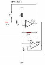
Odd order filters were not covered in the manual. There are a few things I'd like to add. I guess I need another trip with long airport layovers to update it. Here is a way to make an odd order filter on the AF4 board.
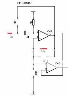
In case the notation is not obvious, the part numbers missing the component symbol are omitted, and the red lines indicate jumpers. Low pass is similar.
Odd order filters were not covered in the manual. There are a few things I'd like to add. I guess I need another trip with long airport layovers to update it. Here is a way to make an odd order filter on the AF4 board.
In case the notation is not obvious, the part numbers missing the component symbol are omitted, and the red lines indicate jumpers. Low pass is similar.
Attachments
Methman - your order went out Thursday. You should receive it shortly.
I don´t need any trace No. I´ve got nice PCB's today. Thanks goes to Jens and Bob.
- Status
- Not open for further replies.
- Home
- Group Buys
- Scalable PSU/regulator GB