I tried again, and spent all day trying to make it better
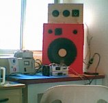
First i modified this diy speaker, using series coils to crossover.
I put a Generator in one "guaranteed flat amplifier" and adjust speaker to be reasonable flat (flat is impossible!)...it is flat around plus and less 6dB.
And i go changing parts in the amplifier...i could transform its sound in something more nice to hear, but quality still inside the "reasonable range"
I still cannot say that i feel it as a good amplifier...well guys, those things are subjective.
regards,
Carlos
Attachments
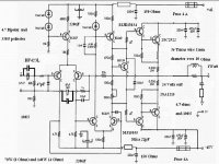
Here is the modified schematic, was tested by hours!
I do not suggest you to make it, unless you already have this amplifier and not satisfied with it.
Here is the modified schematic.
I could perceive increase in quality, i made recordings before and after to check that!
regards,
Carlos
I do not suggest you to make it, unless you already have this amplifier and not satisfied with it.
Here is the modified schematic.
I could perceive increase in quality, i made recordings before and after to check that!
regards,
Carlos
Attachments
Hi carlos,
Thanks for your efforts.
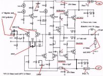
You need to fix the schematic just a little. Add wire from +ve to output device and remove the wire that was going to second output device on the negative rail, it could confuse someone.
What's the point of the fuses now they're are not connected to the output devices?
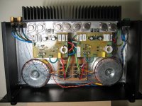
I added a picture of my SC480. Not proud for the wiring....I just wanted to get it finished.
Thanks for your efforts.
You need to fix the schematic just a little. Add wire from +ve to output device and remove the wire that was going to second output device on the negative rail, it could confuse someone.
What's the point of the fuses now they're are not connected to the output devices?
I added a picture of my SC480. Not proud for the wiring....I just wanted to get it finished.
Attachments
Improvements for the sc480 amp
Just for the record.....
I put together a couple of SC480s a few years ago (before I discovered this forum....probably would have built something else if I had, ....maybe..... my budget is very limited and the kits in Australia are very cheap so it was a good option at the time)
Ran with the standard 3055/2955 transistors and was never happy with it. (well I was at first as it was still better that anything I had before.... but I kept harking back to my youth in the 70's when my best pal had 70w JLH amp feeding a pair of large tannoys and my present system just wasn't even close)
So I finally followed jmateus earlier advice to replace power transistors a couple of months ago....used MJL2193/21194.....what a difference!! I was sceptical and expected very little if any change but now the improvement in the bass end is staggering.....much happier now! many thanks jmateus.
No comment on the top end as I am using these in a biamped system and the sc480 is handling the bass/mid only.
I encourage any other SC480 owners out there to do the same. I also replaced the caps he recommended but I'm not so sure about the effect, but certainly replacing the 1uf input cap with a higher quality metal poly cap sounded a worth thing to do whilst I had the lid off.
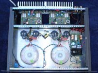
Here is a fuzzy photo of the amp.
*separate power supplies with 8000uf a side (may increase this one day) - voltage is +30/-30 rather than the original +28/-28.
*SC ULD speaker protection kit is fitted on the RHS of the photo and has a 24v Zenner added in series to the relay diode as per Rod Elliots suggestion in http://sound.westhost.com/project33.htm I have also added a temp sensor thermsistor to each power amp heatsink to disconnect the amps if the temp gets above about 65 degrees C.
* In the photo between the power supply caps there is a bridge rectifier with cap and resistor to act as a hum breaker as per http://sound.westhost.com/earthing.htm This was a big mistake...I did not actually have a hum problem and this created one. The active crossover that feeds this amp actually has the RCA shield only connected at one end so using this circuit just added a large resistance to the earth return. This mod has now been (quickly) removed.
* 'Polyswitch' do dads have been removed....hopefully the speaker protection circuit will be more effective and who needs these non-linear devices in the signal path.
Attachments
Kimbo, I was interested in your comments on the SC-480 power amp. I use four of them to drive the dipole woofers in the Linkwitz Orion speakers. I presume you mean you changed to MJL21193/94 output devices (left out a 1) Do these fit on a heatsink drilled for metal TO3 devices? Also, can you remember where you bought them from? A few people have upped the value of the power supply reservoir capacitors which is probably a good idea, but the main reason the output into 4 ohm loads is not what it should be is that the VA rating of the transformer specified by Silicon Chip magazine is totally inadequate. I think it was around 150VA for a stereo pair of amps which is half of what is needed. It is the resistance of the windings that causes the supply to sag under load rather than the ammount of "C"
Keith
Keith
Keith Taylor said:Kimbo, I was interested in your comments on the SC-480 power amp. I use four of them to drive the dipole woofers in the Linkwitz Orion speakers. I presume you mean you changed to MJL21193/94 output devices (left out a 1) Do these fit on a heatsink drilled for metal TO3 devices? Also, can you remember where you bought them from? A few people have upped the value of the power supply reservoir capacitors which is probably a good idea, but the main reason the output into 4 ohm loads is not what it should be is that the VA rating of the transformer specified by Silicon Chip magazine is totally inadequate. I think it was around 150VA for a stereo pair of amps which is half of what is needed. It is the resistance of the windings that causes the supply to sag under load rather than the ammount of "C"
Keith
MJ21194 / MJ21193 (no "L") are the same devices in a TO-3 case.
http://au.farnell.com/jsp/Semicondu...UCTOR/MJ21193G/displayProduct.jsp?sku=9556613
Cheers,
Glen
Keith is correct....the TO3 ones don't have the 'L'.
In my amp the original 3055/2955's I used were the plastic TO-218 cases. Upgrading to the MJL21193 in the larger TO-264 case was OK as I just had enough room to use the existing holes in the heatsink, however the trannies are pretty close together. I found it difficult to get large sil pads in Australia, but in the end as I was a bit paranoid about counterfiet devices, I ordered the trannies and pads from digikey in the states as they are a main distributor for ON-semi....paid a bit more but at least I knew they were the real thing.
There were a few choices for which device to use for the upgrade. Some members suggested the 21193's and some suggested some others types such as MJL15024/15025's. I decided to put the question to Silicon Chip sometime ago and the 21193 is what they suggested. I also asked about upping the quiescent current but the reply was to leave it alone.
I also note in a very recent letter to the editor that someone raised the question of using the amp to drive a 2 ohm load in a car audio application .......the reply was again to use the 21193/21194's and take out the polyswitch.
http://www.siliconchip.com.au/cms/A_109738/article.html
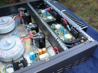
Before....
In my amp the original 3055/2955's I used were the plastic TO-218 cases. Upgrading to the MJL21193 in the larger TO-264 case was OK as I just had enough room to use the existing holes in the heatsink, however the trannies are pretty close together. I found it difficult to get large sil pads in Australia, but in the end as I was a bit paranoid about counterfiet devices, I ordered the trannies and pads from digikey in the states as they are a main distributor for ON-semi....paid a bit more but at least I knew they were the real thing.
There were a few choices for which device to use for the upgrade. Some members suggested the 21193's and some suggested some others types such as MJL15024/15025's. I decided to put the question to Silicon Chip sometime ago and the 21193 is what they suggested. I also asked about upping the quiescent current but the reply was to leave it alone.
I also note in a very recent letter to the editor that someone raised the question of using the amp to drive a 2 ohm load in a car audio application .......the reply was again to use the 21193/21194's and take out the polyswitch.
http://www.siliconchip.com.au/cms/A_109738/article.html
Before....
Attachments
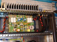
And after..........
- bigger TO-264 transitors fitted - not much room between them!
- SilChip speaker protection circuit in forground modded ala Rod Elliot
- thermsistors fitted to heatsinks
- polyswitches removed
- solen input caps (just vis with red tops) and some silver mica caps
I know it's not at all adventurous/radical/original compared to the amazing stuff I see daily on this forum, but it's been decades since I picked up an iron and I have really got a buzz out of fooling around building this thing (and active XO and speakers).
and in particular checking out this forum.....I love this forum 🙂
Attachments

Glen and kimbo thanks for your advice on output devices. I too have removed the polyswiches and installed speaker protection systems according to an EA design of 1992. I can understand people having a paranoia re fake devices and agree that this is an excellent forum. Have been eyeing off the RMI-FC100 design by roender. A pitty that it is a bit too high to fit in a 2U case. Quasi, of this forum lives a couple of streets away. Have met him but have not paid him a visit.
Cheers Keith
Cheers Keith
No worries Keith!
I've kept the poly switches wired to short flying leads......when I make an amp mod I hang them off the rear speaker terminals as extra insurance seeing as I already have them.......once I'm sure that I'm not about to melt the speakers I disconnect them.
As far as the speaker protection ciruit goes, I'm not sure about the EA design, but after reading Rod Elliots article and circuit ...
http://sound.westhost.com/project33.htm
.... I decided to follow his lead and modified my SC Ultra LD protection circuit by adding a 24 volt zener in series with the relay (D2 in his circuit) to protect against back EMF and possibly increase the speed of the relay action.
Cheers, Kimbo
Need schematic for sc480
Hi everyone,
I need to get hold of a schematic for the SC480 module. I built one a few years back, and my younger brother succeeded in blowing it up. As part of his punishment, I'm going to teach him how to troubeshoot a blown amp.
Unfortunately, the paperwork for the jaycar kit has gome missing somewhere along the line.
Any help would be greatly appreciated.
Stay froody,
Joel.
Hi Joel,
I have the instructions for the Dick Smith version (TO3 output devices). If you don't get a better solution, drop me a PM with your address and I'll post you a copy.
regards
I have the instructions for the Dick Smith version (TO3 output devices). If you don't get a better solution, drop me a PM with your address and I'll post you a copy.
regards
Hi Joel,If you don't have any success elsewhere I've got a spare copy of the full Jaycar SC480 kit instructions which you're welcome to.I can post or scan/email them which ever you prefer.Ian.
in-need of sc480 full article
Hi eanee.
I need full article about sc480 amplifier or jaycar sc480 Kit
Can you please email me
Thanking Alots
Hi eanee.
I need full article about sc480 amplifier or jaycar sc480 Kit
Can you please email me
Thanking Alots
Hi all,
Regarding the SC480, I am thinking of buying the kit from Photonage, but not heavily modifying it (yet). Can anyone tell me what the size of the board is? I am trying to fit 2 modules in a small-ish metal case.
Also, would this unit work ok with a 150mm heatsink?
Cheers.
Regarding the SC480, I am thinking of buying the kit from Photonage, but not heavily modifying it (yet). Can anyone tell me what the size of the board is? I am trying to fit 2 modules in a small-ish metal case.
Also, would this unit work ok with a 150mm heatsink?
Cheers.
- Status
- Not open for further replies.
- Home
- Amplifiers
- Solid State
- SC480 Troubles....