Thanks for the larger image Briansune. Indeed, there is a break in the track near the fuseholder. This was not visible to me when #78 was posted (smaller than now).
As a general guide, try to keep feedback tracks to the input stage as clear from the output stage and power rails as possible. If it must cross other tracks, do so squarely to minimise interaction. The original PCB pattern for this design showed great improvement by paying attention to careful layout.
As a general guide, try to keep feedback tracks to the input stage as clear from the output stage and power rails as possible. If it must cross other tracks, do so squarely to minimise interaction. The original PCB pattern for this design showed great improvement by paying attention to careful layout.
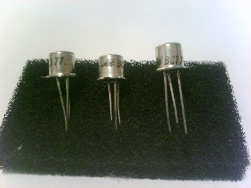
Re: Ian i am not sure that the differential amplifier of the sc480 is good or not but some old designer told me that it is better to add a mirror current in the first stage of the sc480. And i got several BC177 from my school which is very old.
And i would also like to change the trial capacitor into real audio capacitor, the input voltage of the 220nF will be the Rifa, and the output capacitor will be the Wima Black box, what is your suggestion?
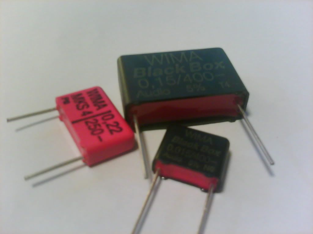
And i would also like to change the trial capacitor into real audio capacitor, the input voltage of the 220nF will be the Rifa, and the output capacitor will be the Wima Black box, what is your suggestion?
You are asking audiophile questions about a utility design?
First, adding current mirrors to the LTP makes a different type of amplifier. Typically, we would class it as a Symasym design.
To get the best out of more complex designs, you have to start with better quality parts like modern semiconductors and very well designed PCBs These are not easy or cheap things to do. Then, if the circuit design is worth it to go to the level where fancy capacitors can make worthwhile differences, it may be worth spending the money.
There is an expression which says"You cannot make a silk purse out of a sow's ear" which means that if you start with something cheap and basic, don't expect to improve it to royal quality by just adding shiny parts. In the case of metal case transistors, you are going back forty years and down in quality, not up. That is my opinion as builder and tester of many amplifiers since the time of those old parts..
However, you obviously have an imaginative view of early electronics so I suggest you buy all the shiny parts you can and have fun, I don't think I can help you there, as we are interested in different qualities. There are many thoudands of design options and it is best you learn about them in the rest of the forum and decide whether you want good sound or good looks as your audio priority.
Hey Ian, i have finished the new board, and i wonder will i decrease the bias setting a bit, and do any one can teach me how to use the flux cleaner case after soldering all the things many flux remain on the board!
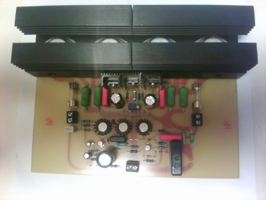
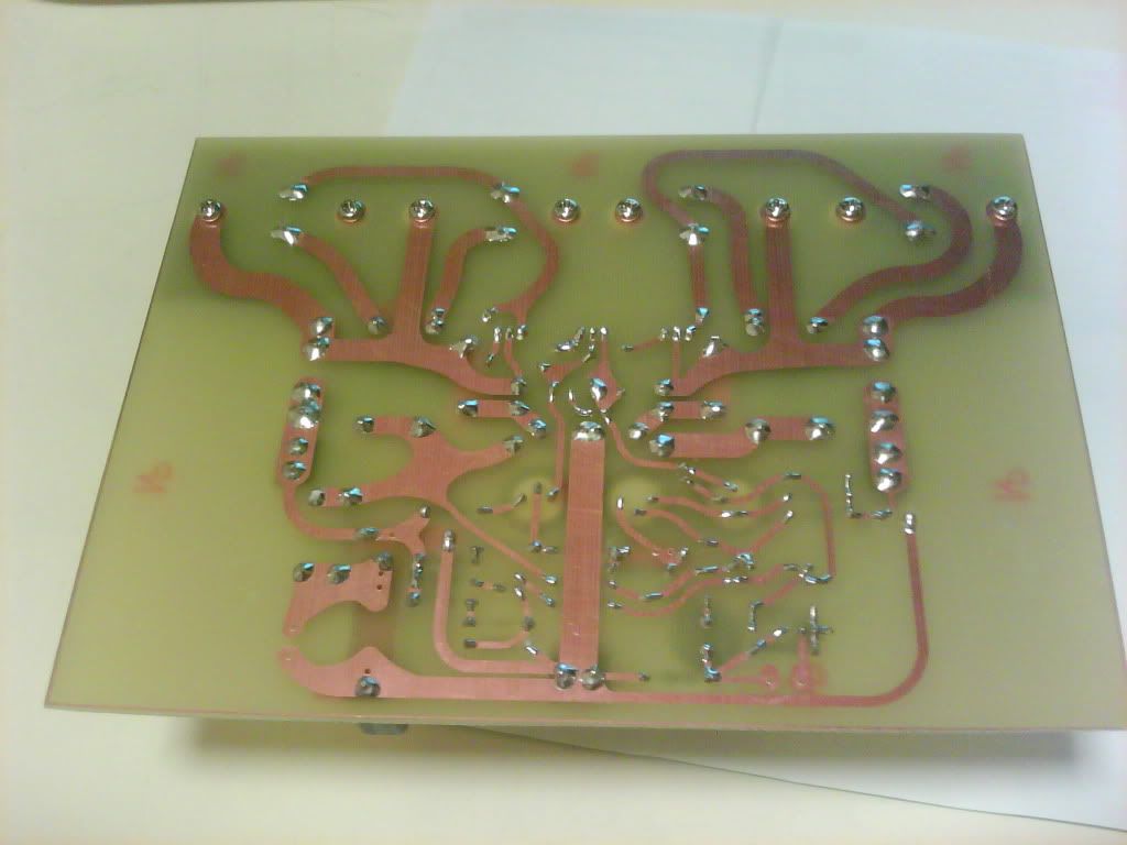
First, your arrangement looks quite neat but you need to take care of some things:
1. Some solder joints don't appear to be properly made to the board - reflow them.
2. You can remove the flux with very hot water even, but alcohol/methylated spirits is good,
using a small stiff brush to scrub it clean. Dry it soon after with a dryer or in sunlight etc.
3. The main heatsinks need to be mounted with the fins vertical to cool effectively, as they
work mainly by convection. That means mounting the PCB vertically too or using a fan to force cool it.
4.The bias of 15mV across Re is minimal. The recoimmended figure is higher (20-25mV) not less,
so if you think it runs hot now,(looking at your small heatsinks, I think it will) consider that it
should be running with 20mV VRe and dissipating even 30% more heat at idle.
I will take your advise: and i brought a flux cleaner which is spirit, and i tried to use it on the board and it is still remained on the board.
I will list the step out:
1 first i spirit it on the board
2 i brush it with an old teeth brush,
3 i clean it with water.
4 dry it with a dryer.
I will list the step out:
1 first i spirit it on the board
2 i brush it with an old teeth brush,
3 i clean it with water.
4 dry it with a dryer.
Hi Briqnsune, Yes, this is just experiment and you only need be careful not to spend much money on special solvents.
It is usually real or synthetic pine tree rosin. (yep - tree sap ) So no big deal.
It is usually real or synthetic pine tree rosin. (yep - tree sap
) So no big deal.Re:Ian as the time goes by, i had finished the second channel, which i measured the output of each board. The output is about 3mV, i think it is still a little high, isn't it?
Meanwhile, i also matched both BC177, and the differential transistor is about 200-205 hfe, i think this will have a better result. My teacher told me, the current mirror design is to control the current flow to both transistors, which equivalent to matches both transistor.
I also check the temperature of the differential transistor, which is about 50-65 when operating, i am afraid that it is quite high. With no doubt, the ST output transistor is better than the Micro ones.
Hi Briansune
Are you concerned about output transistors or differential transistors? You have confused them in your last sentence.
Your teacher may have suggested adding the current mirror to the LTP (input pair). There is a big mistake there if these transistors are getting hot because they should only be sharing around 3 mA. This design problem is something your teacher can resolve, since that ;s where the error arises.
If your output transistors are the ones that run hot, I have already mentioned that the heatsinks are likely too small. This is not an arbitrary matter, you need 1 degree C/ Watt or lower rated heatsinks for each channel.
OK the LTP is clear, but the ones who are getting hot is the 2N3019 and the 2n4033, which is unexpected, due to i have measure the bc639 &640. When these are operating the temperature is about 45-55 deg. but the 2n3019 4033 is about 60-70, very high in temperature. i don't know why?
Reply also the concern, i have change several output transistor, which turns out the micro ones is the worst. ST and ON are the best.
Reply also the concern, i have change several output transistor, which turns out the micro ones is the worst. ST and ON are the best.
The output transistors have been discussed previously. There will be little difference between brands in this application,
where they are scarcely working, yet as advised, ST have an edge with Ft.
I've also made it clear about the unsuitability of those quite different TO39 VAS transistors. They are not interchangeable,
neither are their dissipation ratings sufficient.and this result was predictable. There has been no indication of the increased
bias on the VAS itself. You should measure this by calculating from the voltage across the VAS series resistor to the neg. rail.
Parts are selected from the circuit operational requirements not from generalised descriptions or how wonderful they look.
Last edited:
Dear Ian: i have a problem again! This is really serious, which the sound of the amp becomes very Baked hot. I don't understand, i really can't keep listening! And i think the amp is not giving out any second harmonic. Which when i listen to the amp about 4mins. I really don't understand. I am really giving up!
And i brought several MJ15024/5 could i replace it?
And i brought several MJ15024/5 could i replace it?
Hi Briansune
I don't know all the changes you have made to the basic SC480 design but it seemed that you were substituting parts, adding a current mirror using old TO18 types to do that, last you told us what you were doing. We could see this problem coming.
When adding a Current Mirror, the basic frequency response and required compensation of the amplifier is changed, so calculations and adjustments for this have to be made to preserve amplifier stability. i.e. You can't just modify circuits unless you know how they work and how to compensate for the DC bias and AC response made. This is a significant change and I would expect instability (oscillation) to occur in the amplifier. This will often give a "brittle" hard sound and overheating in the VAS and output stages.
SC480 is not a bad circuit, probably you just don't understand the design requirements. As previous, you need to study audio electronic design, since playing with parts but no suitable test instruments and procedures only gets things to work by accident. Mostly you get smoke unless you stick to proven designs, simulate their operation or learn properly. The amplifier can still be made to work by changing the frequency compensation caps (68 pF IIRC) which are fitted across the differential VAS transistors (BD139 or BC639). However, this is not simple and needs to be thoroughly investigated and tested, as was the original design. I don't recommend you try this without adopting such a complete and proven design.
So, restore the circuit to the original spec. components and circuit, especially the input stage as the CM (unless the changes are properly compensated) is wrong and the VAS types not best suited. The MJ15024/5 are high voltage types for large amplifiers but will still work fine here, as would MJ15003/4.
Eventually you have to decide whether you want the amplifier to work as designed, or not so I think you need to drop the idea of designing by the looks of transistors. You may succeed by adopting an old (1967-75) design but not modern designs that generally use higher voltage parts.
Good luck restoring the original and hearing good sound instead.
Oh Ian i think you miss understand my amp, i never add any current mirror or others design in it. I only replace different transistors. I know 2n3019/ 2n4033 are not really the best choose.
As the problem begins, i started to replace back the Bc639/40 into the amp, the problem still continues happen. I really don't know why. I just use different transistor to compare the output result.
The first class gain of the amp won't require any current mirror, cause the gain will change by that action. And the second decrease gain is to reduce the gain level, this is control by the transistors BC639/40. So in this part it is crucial. 2N3019/4033 is warmer than the BC639/40 this might leads to the temperature of the transistor. But this won't last long, cause the transistor is operate in high temperature level! And the BC639/640 is sharper and cleaner. All things is fine before 4mins! After several mins all things getting worst!
I don't understand why! The OPT heatsink is not large enough? Will the problem leads by the biasing? or the voltage supply and the OPT model?The transistor is fake? I keep question myself!
Regards!
Last edited:
Hi
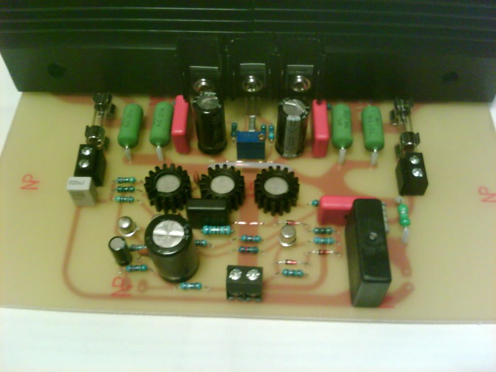
You did describe what parts you were going to use in a CM. However, it is good this didn't go ahead. I commented on the heatsink size before and 1 deg.C/Watt rating is required but the sinks you used appeared too small but have you added fans? The rating should appear on the supplier's spec. sheet downloaded from their catalogue. Unfortunately, you used 2 heatsinks, so there will still be problems sensing the temperature correctly. Always follow designs closely - at least look at the SC website pic.
Is this problem the same in both channels? It is likely you do have oscillation and/or bias problems, so check that the Vbe multiplier, a BD139, is insulated but attached properly to one heatsink so that it can track temperature. Recheck the bias as the amp heats up in the 4 min, to see what is going wrong. Otherwise, overheating with normal or erratic bias level indicates oscillation but to be certain, an oscilloscope is needed. Also, recheck all transistor Vbe (~0.65V) for correct operation.
Oscillation is not simple to cure and it is good to search the subject here on DIY audio or Google it, as DIYaudio will give many hits. This is a topic to study, as suggestions are not always helpful without instruments. I recommend textbooks rather than comments on forums, as good authors discuss subjects systematically, with the aim of your proper understanding.
Could you possibly tell me the voltage value of the collector of the BC639/40 cause the supply is 38.6V +-.
This can decrease the troubleshooting of the amp!
I notice the heat sink problem as well, so i have add fans on it!
And the data of the heat sink is not provide, so i don;t know how to measure that data,
Regards!
This can decrease the troubleshooting of the amp!
I notice the heat sink problem as well, so i have add fans on it!
And the data of the heat sink is not provide, so i don;t know how to measure that data,
Regards!
Hi Briansune
I don't have the schematic or a working amplifier any more to give you real measurements but the collector of the left side BC639 will be unbiased at around 0V and the right side will be at the lower driver base bias voltage of ~-1.3V, as set by the BD139 Vbe multiplier.
As this is a forum, it would be considerate to post your edition of the schematic for everyone to read and understand what is being discussed and make other suggestions if they wish.
Reduce your supply voltages to +/-35V. At least to <38V as previous, whilst you have problems. Problems are solved by eliminating errors and I have said that your regulators will malfunction whilst ever you persist trying to use them out of specification (at Vin-Vout < 5V). This will continue to cause problems until you correct it. Measure this voltage. It may sometimes be >5V idling but think what will happen when the load (power output) increases? I suspect it produces distortion as the signal varies and the reg. is forced to switch in and out of operation. Remember that the reg. voltage is fixed WRT ground, but supply voltage drops with load, so the differential you measure when idling always reduces according to the signal when driving a load.
Ian could you teach me how to balance the amp with a extra circuits, the gains of both circuit broads is totally different! The difference is really huge, i think if i mention it with data is could be about 1-2dB different! Could I add a balance potentiometer in it? This will goes to the input, if my knowledge of the balance circuit is correct.
Hi briansune
1-2dB difference is not immediately obvious. I think you are talking about something much greater and logically, this means you have an error(s) with components, soldering or your source/cable. Check your work and compare DC voltages around the input stage transistors. It is very easy to misread resistor colour codes, for example, so recheck values with your meter.
Fix this and you won't need to mess with with balance controls. You should browse the analogue line level forum here for preamplifier schematics or look at the schematics of integrated amplifiers that get posted here for clues to how balance pots are wired. It's not difficult but the problem is to buy a suitable part - you often can't, unless it is part of a car system or includes buffer amplifiers.
One obvious solution, until you find the real problem, is to fit single volume pots rather than the stereo pot. When you measure the difference necessary for balance, you could also calculate a potential divider of 2 resistors to add to the appropriate channel of the stereo pot. to do the same job.
Last edited:
- Status
- Not open for further replies.
- Home
- Amplifiers
- Solid State
- SC480 Amp Questions