OK, lets get to basics again.
You show only 3V drop across the regulator. It cannot work as intended with such small difference even on pure DC supply that does not drop or show AC ripple like the rectified AC supply from the rectifier will. You may get adequate regulation from that transformer if the regulator was set for > 5 volts drop, with just about 2 amps load current. If you understand the application notes you will see this is how regulation is done. The supply from the rectifier is not smooth DC, it is rough, jagged peaks that average to 43V but drop as low as 35 under load so to regulate you must have the voltage set to allow for the maximum drop or the regulator will stop working and make noise. (maybe that's what you hear) This is important to know about linear regulators. Please google application notes and read. The diagrams are there in most issues from National or Texas now.
If you want to experiment, change R2, R12 to set output voltage down to 38V and listen for that noise again. You may be surprised. Then continue as I asked you, to reset the amplifier current - not the power supply this time, please.
Last edited:
Just in case, the first point you have mention is that the linear regulator will goes down while the voltage is not enough for dropping; when it is loaded.
step 1:
The second point is that by reducing the output voltage Vs < voltage supply into 38V
step 2:
Reset my amp bias as well
If i do the maths output = 30*1.414 - 1.4 = 41.0V
Vpp = 1/2fC = 0.707V = 700mV
After the first 2 capacitor of my rectifier, then into the linear regulator< in deep it is still high for that ripple rate.
OK IAN i had finish all the steps which turns out one thing, the noise is come from the source which means it is not the amp itself!
But i still finish all the step you had said, which bias at 15mV, both are tried with the other CD player, turns out it is clear and sharp!
I still have one question in deep< the voltage 38V is lower than required, although we higher the bias current, what is the bias setting of shifting the BC639 & 640 into 2n3019 2n4033?
cause i am still studying the fundamental@@
The point you make about the output voltage being > 41V is correct. "Average reading" DMMs show 43V with unloaded transformers
~200 VA. True RMS meters show a bit different.
When the transformer is loaded to its rated maximum current output, the voltage will drop to 30VRMS and allow 41V DC output with
sufficient capacitance. This is the rated performance. The formula for ripple current actually has load current as a factor in that simple
equation. I /2*F*C.
If I=3 amps, ripple voltage will be 3* what it is at 1amp or 2.1Vp. (the typeface is confusing, because I is not 1)
Those are theoretical figures describing the ripple waveform but make no allowance for the voltage drop across (probably 4) emitter
junctions in the overall regulator circuit. Now you have probably 4*0.65 = 2.6V drop also to consider, assuming there are no further
circuit resistances such as wiring and reference resistor drops to consider. The losses do begin to add up, eh?
I gave you minimal allowance figures for a low current supply from your high current transformer and I suggest 5V since 2.6 +1.7= 4.3V
with no allowance for losses or actual peak currents. Looking at ST Micro application notes, the minimum voltage drop from overall
regulator circuit in to out nodes, with smooth DC is 3.5V for currents up to 10 amps with boost transistor, as you show.
So, 5V total is still on the edge, right?
AMPLIFIER - I'm glad the sound is good and I hope what you like to hear. A drop of 2 volts to the rails with a regulated supply is less
than normal unregulated supplies with smaller transformers, so this is no problem at all. If you want to use the TO39 parts in the VAS,
they require the same bias, so no changes, The problem is the power rating, so feel the VAS transistors and see if any are hot and
consider if a small sink may help with keeping them cool but this may not help much in the actual duty. Try them if you wish.
They will be less stressed now but I fear still outside Safe Operating Area. Don't bin the BC639/40. You will need them if the amp dies.
SOUND QUALITY - Is this good enough for your liking? It uses cheap parts for cost reasons but the real difference is in the output
transistors, as advised earlier. MJ15003/4 are a basic improvement and the best you can get in TO3 parts is MJ21193/4. Let me know
of anything better that is not too expensive. You can buy these parts anywhere in HK as I do by internet.
Please,tell everyone what you think of the sound. 😎
Last edited:
sure it is I/ 2 * f * c, i just use 1Amps as an example data.
The point is right, sure i look into the data sheet it tells me one thing; the Line regulation KVI is 0.03% max when 3V< Vin-Vout < 35V
So we do the maths again the Vpeak of the output will be 41V when no loading, if i want 40voltage 41-30 =1V which is not enough so you told me to use 38V this is because it is just at the edge of the regulator: 0.06% will turns out 0.0228V best error. And KVO = 1%
how about the voltage increase of the MJ15003/4 & MJ21193/4
Will it still possible to turn back into 40V and re set the bias? cause there must be a reason for that design of the regulator, sure i must be wrong few days ago the real noise came from my old CD player which is with me over 3years. @@
In fact all the components are still cheap due to testing process, but i am going to change the output resistor the error is too high in that place while i measure the voltage across it shows all four different values. I think i will still choose the company Magnatec, because it is made in UK, i believe UK than Malaysia ST company.
Now the sound is not confirmed, because when all the things get back together, noise travel started a party again, which i hope the party is not that big@@
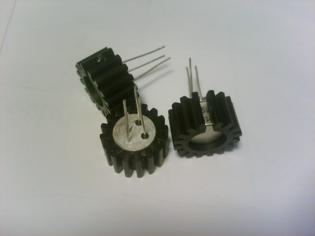
After replacing all the things, i will post some pictures, I love metal can package is because the old style transistor sounds is different than plastic.
MJ11016/5 will it be ok, because it is a darlington type transistor? And i am going to change the resistor into Arcol resistor.
And i brought the BC107 in stead of the BC557 TO-18 package as well.
Most of the metal can package is not cheap now, due to the plastic one, but there are still are not, but as i want to improve sound QC what suggestion will you think, the output stage < of cause MJ transistor is been here a long time any other? such as BU model?
The point is right, sure i look into the data sheet it tells me one thing; the Line regulation KVI is 0.03% max when 3V< Vin-Vout < 35V
So we do the maths again the Vpeak of the output will be 41V when no loading, if i want 40voltage 41-30 =1V which is not enough so you told me to use 38V this is because it is just at the edge of the regulator: 0.06% will turns out 0.0228V best error. And KVO = 1%
how about the voltage increase of the MJ15003/4 & MJ21193/4
Will it still possible to turn back into 40V and re set the bias? cause there must be a reason for that design of the regulator, sure i must be wrong few days ago the real noise came from my old CD player which is with me over 3years. @@
In fact all the components are still cheap due to testing process, but i am going to change the output resistor the error is too high in that place while i measure the voltage across it shows all four different values. I think i will still choose the company Magnatec, because it is made in UK, i believe UK than Malaysia ST company.
Now the sound is not confirmed, because when all the things get back together, noise travel started a party again, which i hope the party is not that big@@
After replacing all the things, i will post some pictures, I love metal can package is because the old style transistor sounds is different than plastic.
MJ11016/5 will it be ok, because it is a darlington type transistor? And i am going to change the resistor into Arcol resistor.
And i brought the BC107 in stead of the BC557 TO-18 package as well.
Most of the metal can package is not cheap now, due to the plastic one, but there are still are not, but as i want to improve sound QC what suggestion will you think, the output stage < of cause MJ transistor is been here a long time any other? such as BU model?
Last edited:
Hi, you ask about old parts and the simple answer is that they were designed to use in old amplifiers with low voltages and power output. Look at Vceo,Vcbo. They can sometimes be used but usually, the circuit needs redesigning to reduce voltages the parts are exposed to. This is difficult at the VAS, drivers or output transistors, so it leaves you with just the input stage to redesign. Is it worth it for a couple of tiny transistors that are hidden when the cover is on?
The Magnatec PNP3055 has no complement as already stated, so no point.
ST Micro parts are superior to Onsemi for audio quality, with TIP3055/2955 style best. (look at Ft even) don't imagine ST stuff is no good.
Forget power darlingtons and switching transistors - shop elsewhere.
To use old, low voltage parts, cascoding with more transistors may be necessary or by lowering the power supply to 30V or less for around 25W output may be helpful. There may be expensive types that can be substituted but that is for you to investigate for fun if you have the money and time to to spend.
When substituting these power transistors, as previously advised, no voltages need be changed, you simply exchange and trim bias again. If you want to make use of the simple transformer power supply, the rail voltage will increase to 43V unloaded again so you have to upgrade the VAS as detailed before. That means no metal cans, right? so decide what you want to do and do it, because you cant have it both ways, it should be obvious.
At this point, we are looking for you to identify the noise which you aren't clear about so we can't be sure your power supply is not causing problems. We're done going over and over metal semis - that is for you to discover and others might want to join you. Let's just get it finished as designed and working reliably.
Reply: the problem source!
I just finish the testing again, which i discovered that the noise was came from the CD player; What i am doing is try to increase the voltage back to 40V and bias it, meanwhile i don't heard any hum or noise. So i am sure it is the CD player, i think it is because the CD player was shorted once. I think i am not requiring the high power at all, in this moment, cause the 20W is enough (My speaker only max to 60W), but i choose the SC480 is because it is common. I hope i can do some improvement as well, you really teach me a lot THANKS you are a good teacher@@ aren't you?
I prefer the Magnatec is because it is UK staff at all, ST things is good, it is found easily in HK. But i am not sure that the TIP model, why TIP is better than 2N model? Due to the latest plastic case or other? Just curious, in deep the TIP model is easy to mount, TO3 is damn!
There could be an earthing (ground loop) problem with the CDP. I think your mains supply may have no separate ground pin, which makes it difficult to eliminate low level hum problems when connecting devices with inbuilt power supplies.
The problem with Magnatec is only with complementary devices (none), So it's kind of hard to prefer a supplier with unusable parts.
I have explained to you why you should not raise the voltage to 40 V when the supply is now regulated. You will certainly blow 60V transistors with moderate power because the supply does not immediately drop as it otherwise would, since the specified power transformer was quite small. Instead, you have a large transformer which will not drop much under load so think about this and the contradiction in what you say about not needing much power but now wanting maximum supply voltage, what are you trying to say?
Actually, I would lower supply more, not raise it, because you don't load test and when the supply does drop out of regulation and cause VAS and output failure by 40W dissipation level (not output power), it will be annoying. Let's be clear about this, the amplifier can tolerate maximum voltages limits with no load but if you drive significant power into a load, it must be de-rated because the power capabiliy is much less at full voltage, (Safe Operating Area) so please stop raising the voltage beyond already exceeded SOA limits and regulation capability.
The amplifier cannot withstand 40V regulated supplies at full power. It was designed to have simple supplies that dropped with load - understood? We go over this time and again and still you feel compelled to push magic maximum 40V and imaginary regulation from series regulators that can't operate with such reduced margins in your application. There is zero margin for the boost transistor, power fluctuation, losses or parts tolerance - so why guess that it might work at ~8 amps peak with probably only 1V differential across the regulator?
The problem with Magnatec is only with complementary devices (none), So it's kind of hard to prefer a supplier with unusable parts.
I have explained to you why you should not raise the voltage to 40 V when the supply is now regulated. You will certainly blow 60V transistors with moderate power because the supply does not immediately drop as it otherwise would, since the specified power transformer was quite small. Instead, you have a large transformer which will not drop much under load so think about this and the contradiction in what you say about not needing much power but now wanting maximum supply voltage, what are you trying to say?
Actually, I would lower supply more, not raise it, because you don't load test and when the supply does drop out of regulation and cause VAS and output failure by 40W dissipation level (not output power), it will be annoying. Let's be clear about this, the amplifier can tolerate maximum voltages limits with no load but if you drive significant power into a load, it must be de-rated because the power capabiliy is much less at full voltage, (Safe Operating Area) so please stop raising the voltage beyond already exceeded SOA limits and regulation capability.
The amplifier cannot withstand 40V regulated supplies at full power.
It was designed to have simple supplies that dropped with load - understood? We go over this time and again and still you feel compelled to push magic maximum 40V and imaginary regulation from series regulators that can't operate with such reduced margins in your application. There is zero margin for the boost transistor, power fluctuation, losses or parts tolerance - so why guess that it might work at ~8 amps peak with probably only 1V differential across the regulator?say about not needing much power but now wanting maximum supply voltage, what are you trying to say?
The design of that regulator makes me can't understand what's going on. But after mentioning the SOA it is quite clear what's the point.
While i increase the output stage, more power will deliver to the amp. In this case the power range will increase as well. More power is good, but i found that i can't use the maximum at all , because at 20W it is enough for my speaker.
I think continuously change the output transistor is the best way to improve sound QC, but without upgrading the output power any suggestion?
Briansume, You were trying to restore maximum voltage (unregulated) when you have a regulated supply. The meaning of regulate is to say that the voltage stays constant with a varying load. If that is the case, the amplifier will have greater average supply voltage thus likely to fail at quite low power because SOA is soon exceeded. If you do in fact understand SOA diagrams, you will have no trouble accepting that likelihood.
What I have asked you to do is refrain from raising the power supply voltage because:
1. you do not need the extra power capability,
2. The extra power output will destroy the amplifier.
3. The regulator will cease to function at all.
4. High noise and distortion will sporadically break in on music peaks.
I have given you the best available suggestions twice already. You do not need to use different ones and frankly, unless you research and locate suitable Japanese TO3 types, you won't find any more good audio types other than maybe MJ15021-4 series since most are now obsolete. Just swap and enjoy. You are not changing the amplifier or any other parts so there should no changes required yet, other than reduce the supply voltages to between +/-35 and 37V and reset the bias for the new components. Just do it.
OK IAN i will take your advise, Japanese TO3 type might take time to discover, and i am reprinting the board in EAGLE as you said TO 39 or TO 18 package will require heat sink. I hope i can finish it as quick as i can. Share some of the picture will be the best.
Adding a heatsink is just a part of a solution. Only VAS TO39 types may benefit from a quite small heatsink and this does nothing about signal peaks, clipping behaviour etc. exceeding SOA limits. Test those transistors already fitted. Do they get warm? If so, similar is likely with TO39 types. Be sensible about which parts you may need add sinks to.
If you keep the rail voltages <38, the devices may survive - who knows when you push parts beyond sensible limits?
If you keep the rail voltages <38, the devices may survive - who knows when you push parts beyond sensible limits?
Rely for: Be sensible about which parts you may need add sinks to.
TO39 heat sink is easy to found and mount, but TO18 do not
i have check that the BC107 is better than BC557< i saw it was. But i am not 100%sure.
Heat sink require space, redesign all the parts and put them back is a test. I am still working on eagle. Post it out after it is done, hope you give some suggestion as well thanks. Below 38 voltage it is find because those transistor is a bit higher than that of the BC639 BC640.
What I am saying here is; Don't fit sinks to anything unless it is likely to need it. Only a tiny sink may be necessary on just one so don't buy huge stuff just because RS doesn't have a selection.Only VAS TO39 types may benefit from a quite small heatsink sink .....Test those transistors already fitted. Do they get warm? If so, similar is likely with TO39 types.... Be sensible about which parts you may need add sinks to.I
BC107,147 are low voltage predecessors to BC547. Better or worse is just imagination unless you compare particular specifications and perfoemance data such as Vceo, Vcbo, case style, leads, max.dissipation etc. why not read the data sheets?
Last edited:
YS YS in deep, and i did order any heat sink in RS. And i think i am getting into trouble, i just found out the BC107 is a NPN transistor damn. And the BC177 is stop producing many years ago. So i think i need your help, will it possible to replace the BC557 into BC478, which i think the max Vce is not enough? And i check the DC current gain is just the same as the BC557.
BC478 is a audio pre-amp transistor. As it said in the data sheet.
BC478 is a audio pre-amp transistor. As it said in the data sheet.
It seems you can't understand that no means no. Please don't try to substitute low voltage transistors for higher voltage types. The circuit has to be revised to allow low voltage types to be used. It may not be just the addition of resistances as this will also affect the amplifier stability, gain and compensation requirements.
You won't find equivalents from 45 years ago so don't try and redesign the board for unobtainable or unusable parts. If you want an old style amplifier, it would be much better to find a design from that time (1970 or earlier) that will give genuine antique audio quality as well.
These will use mostly lower voltage transistors like BC107,8,9 and BC157,8,9 snd will have a very different VAS design and a lower, single voltage power supply.
Leave what works alone and use your amplifier as it was designed, whilst you learn and track down the design and parts for another, antique amplifier.
Sorry about that, i am still working hard on those fundamental. And i discover the TO39 transistor is very hot, during operation i use the IR device to check and got almost 43C. Then i add the heat sink, and all the setting is same as you said. 38 rail to rail and reset the bias while it is warm up.
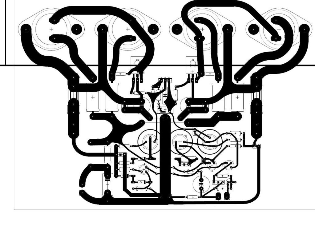
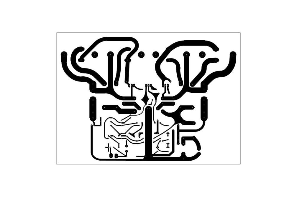
Hey Ian i have design the board, the first version is draw by hands and i would like to print it by UV Lamp.
Regards
Regards
Hi Briansune
i guess you realise there will always be errors in the first few drafts of PCBs. For instance, you have the R/S
power rail (fuse holder) connected to ground. The sparks will be a sheet of flame as the copper burns.
The traces to the small eletrolytics seems too fine. I would increase all fine tracks where possible. The base
leads to the output transistors can be much thinner. here may be more errors, I only noticed those 3.
Last edited:
- Status
- Not open for further replies.
- Home
- Amplifiers
- Solid State
- SC480 Amp Questions