Hi briansume.
I hope you mean that B-E voltage is actually ~0.65V, not ~6.5V. If so, its is OK for the bigger transistors to read lower, even 0.58V, with the small current flowing.
When the bias potentiometer is adjusted correctly for optimum bias, you should have about 2.4V DC output from the bias generator, as read across the MJE340/350 bases. It should also be adjustable, just as we discussed the bias current in the output transistors which it controls. Note that it is the bias current that is the most important.
20 mA total current in the amplifier is too small. Here is what most simple class AB amplifiers like this one should read:
Input stage 1.5 - 2.5 mA
VAS 8 -20 mA (this is a "balanced" VAS, so more current)
Output transistors 25 mA/pair for lowest THD or "optimum"
Adding these currents, a figure of 40-45 mA would be closer to correct for total current with no load, so I think you still have bias problems. Check rhe current flow in the VAS by measuring the voltage drop across the common resitor at the bottom of VAS schematic, where it connects to the negative rail. Sure, you will have audio and never have thermal problems without enough bias but the sound will be awful. ,😱
Hey Ian,could you send the upgrade MJ15003 to my e-mail address, case i would like to increase the power of the amp? graph or circuit diagram might be the best.THZ the amp are well operate. THZ for teaching me.
I don't think you need any schematic of modifications to upgrade the output transistors. Other components mostly remain as before, so MJ15003 & 4 are convenient "drop-in" replacements for the 2N3055 & MJ2955 pair.
If you wish to use the higher rail voltages, I suggest replacing the VAS transistors with >100V rated Vceo types, as already described. There are several old colour TV video driver types which have the speed and gain required here - and you should slightly increase (~15%) the resistor in the input stage current reference to keep the small current there the same and also the common collector resistor connecting the VAS to the negative rail.
This is simply to maintain bias currents which would otherwise rise with increased rail voltage.
That's 2 resistors and 5 or 6 transistors, depending on the suitability of your bias generator transistor. The best choice for this is usually a T0126 style transistor like BD139 but it is not critical at only a few volts, so ratings are not important, just good thermal (not electrical) contact to either output transistor case or the heatsink, which is easier but not as effective.
A little more work and it will be sounding better 🙂,
YS thanks IAn the ideas is quite good to unchange the components and replace the push pull transistors, cause i found out that the 3055 &2955 is not the things that i expecting after few hearing. i thought it is because the transistor have a little bit burns out. But reply to your post i think the reason have comes to the ending, which is the 2n3055 is quite harsh(I think you know what i mean the sound base does not have any taste in it.)
Some people told me that metal case transistor is better than plastic one, in this part i'm not that sure, is that true? cause i have heard the 2n3019 and 2n4033 transistor and only quite frequency have different, but not much. What do you think?
Some people told me that metal case transistor is better than plastic one, in this part i'm not that sure, is that true? cause i have heard the 2n3019 and 2n4033 transistor and only quite frequency have different, but not much. What do you think?
Metal Case transistors
Hi briansune
You ask a complex question. As far as TO3 power goes, most inexpensive types are very old technology and so are not very linear devices and have low gain and frequency capabilities. Audio quality suffers generally but some designs seem to avoid the harsh sound better than others. Their best quality is their proven reliability in certain power applications - not usually audio though.
I believe that amplifiers using multiple output transistor pairs of any audio type can still sound good, especially at modest levels where linearity is a much easier task.
As we go down in chip dimensions and power, the difference may not be much at all in some audio applications as say, BC109 compared to later BC549. 550 etc. which we still use, even though better specified parts have been available for decades.
I believe that people attach quality to old, solidly cased and expensive components because they look better and served grandfather well. Personally, I know this is not a valid reason and proven, superior parts with more suitable specifications, easier mounting and good prices are widely available.
Unless we are attempting to build artworks, I think we should stay with modern, affordable and widely available parts which can still be contrived to produce the "old-time distortion" if we wish it. It can't be easily done vice-versa, though.
To see what most guys here on DIYaudio think are are suitable "throuh-hole" or leaded parts, check out Greg's Website which I referred to earlier. He did invite others to contribute and the list is good with clear application categories and easy use for anyone sourcing parts for projects here, via international sellers but you may have other sources with different parts. It is instructive to download free datasheets for yourself and compare the important qualities like Vceo, Ft, Cob, Hfe linearity as applicable to the different roles for audio parts. You can learn much better with facts that you understand than opinions too! 🙂
Finally, I should remind you about bias setting. Sound will be awful from any linear amplifier like this one, unless you get bias up to ~25 mA through the output stage, per output transistor pair. Class AB amplifiers require this for optimum low THD but many DIYs prefer overbias to get progressively more class A operation at the cost of more heat with the likely need to redesign the controller and also introducing another, lesser distortion. Make sure you get this right first - I ask because you don't refer to it in your amplifier.
You can navigate to the front page and the transistor spreadsheet from here;
http://users.tpg.com.au/gerskine/greg/silicon chip sc480.htm
Last edited:
Hey Ian Have you ever heard about the PNP type of 3055
PNP3055 datasheet and application note, data sheet, circuit, pdf, cross reference, pinout | Datasheet Archive
Will it possible for replacing the MJ2955?
PNP3055 datasheet and application note, data sheet, circuit, pdf, cross reference, pinout | Datasheet Archive
Will it possible for replacing the MJ2955?
PNP3055
Heh,heh 😀 - nice try briansune but pnp3055 is an N-channel MOSFET!
IIRC, there is another part called MTP 3055 and these are intended (it seems) to replace 2N3055 in some applications where the identity is similar to the original.
No, you are stuck with MJ2955 or the slightly better TIP3055/2955 pair which I prefer for audio as they have slightly lower distortion and easy TO247 mounting.
There is still a big range of parts that are not much better than 2n3055 and perhaps you know better what is available in your location. If you have access to RS components, Farnell/Element 14, Mouser or Digikey etc. the slightly higher cost of modern parts is easily offset by the much improved quality. Do you have access to such suppliers?
ha ha Ian you are really smart, i usually brough components in RS. Cause the component is free sent to my location.
But what's the point to not replacing the MOSFET transistor, cause i had checked the datasheet which is quite same as the TTl one, for example the Vceo Vcbo.
But what's the point to not replacing the MOSFET transistor, cause i had checked the datasheet which is quite same as the TTl one, for example the Vceo Vcbo.
Last edited:
OK. I guess you are not aware that FET and Bipolar Junction Transistors (BJTs) are fundamentally different solid-state technologies. You need to read this for yourself and then check the standard bipolar (like SC480) compared to MOSFET designs. This will show how the output stage differences are met. You can start with Google and Wikipedia and then read some schematics in threads here.
Sure, you can have similar maximum ratings for Vds,Vce but that does not make them operate the same way or make up for very different bias requirements, input capacitance, linearity curves and lower transconductance. If you want a Mosfet amplifier, you need to start a new PCB with a redesigned output stage to suit the particular FET type.
Unfortunately, PNP/MTP3055 are switching types so are unsuitable for audio. Lateral Mosfets such as Semelab's Alfet or Exicon brands or linear V-MOSFETs such as IRFP 640/9630 are among the relatively few Mosfets that are OK for audio.
When you have the basics of solid state electronics, choose a good book on audio electronics in your language and study. Bob Cordell's and Randy Slone's amplifier books discuss Mosfets and are widely available but I have no idea of translations or E-book availability, which could be better for you. Few people will ever learn enough to be competent but it is important to have a good, basic understanding of the parts we use in DIYaudio.
We are well off-topic now. Electronics and different designs should be left for another thread. I still think your best option is to use a 2SC 5200/2SA 1943 or FJP5200/1943 etc. output pair.These are cheap but offer an immediate drop in THD. Note that your driver pair must have plenty of current capability to drive 2N3055s which have awful gain linearity, falling to about 15 when they are working. Nope, 2N3019/4033 will not do here. They will soon die. MJE243/253 or KSC2690/A1220 are much better drivers for lazy old output transistors. 😉
But i really need to reply one thing that is the PNP type of 3055 is a TTL model type, this is shown on the datasheet which is only found in the Magnatec company. I hope i will brought it as soon as possible and reply to you soon.
http://datasheet.octopart.com/PNP3055.-Semelab-datasheet-542719.pdf
http://datasheet.octopart.com/PNP3055.-Semelab-datasheet-542719.pdf
Oops!
Indeed, you are correct. I ignored the fact that there are more than one specification of PNP3055 - very unusual and confusing! The Magnatec version is BJT as you say, with Ft much higher at 4 MHz. On-semi spec. for 2N3055 is only 800 kHz.
Unfortunately, I can't locate a similarly improved (Ft, gain linearity) NPN complement to that model but I guess it would substitute OK for MJ2955. It may well be a superior part but that likely will not make any improvement alone in the complementary application.
If you want to improve the audio, you need to significantly improve both output transistors and they need to be closer matched complements with higher Vceo. The combination is unlikely unless you adopt newer parts. If you insist on TO3 style, the better and much higher power MJ802/4502 are a good match. However, there is no magic in old silicon or full metal cases - the appearance of shiny metal is another story.🙄
Ya Ian, cause i have find out that the suggested Transistor is not easy to found (In my city). So i might try finding it out.
I always felt the metal cases is full of mystery, and the temperature rate is quite higher.
I always felt the metal cases is full of mystery, and the temperature rate is quite higher.
Hey Ian what a long time, i think i got a problem again within the double check and i set the bias with the 560 ohms in 28V which gives about 50mA rail to rail so after few weeks the problem started, the amp turns out some hum which is em em em the noise is very small, what's the point all the things goes right?? Hope you can help
REGARD!
REGARD!
Hi Briansune
Can I assume this a pulsing hum?. If this is so, it's more likely caused by external noise from your electricity supply. You may find that this noise is not always heard, 24/7.
There are many reasons for power being noisy and every year or so, we need more and
more protection for our audio gear. Simple DIY amplifiers have almost no protection so they are very vulnerable to interference of all kinds..Check the earth connections of all your leads inside and out of the amplifier (I hope you have it in an earthed metal case.
Next - Do you have regulated supplies to the amplifier? If you do, you could try adjusting the capacitance after the regulator from 10 -470 uF and see if there is improvement or change to the pulsing. There could be interaction there which causes the pulsing. The next possibility is "motorboating" - a feedback from the output to the input of the amp by bad wiring layout, signal wires not separated or shielded.
So you have some things to look at. To suggest parts you can access, do you still buy from RS Components - HK?
BTW - take a look at recent posts by Nigel Pearson in the "Nap 140 kit on Ebay" thread. There is a simple regulator design that allows straight 50V supplies to the output stage and regulated 40V supplies only 40V to the rest of the amp, It's not exactly what you need but is good to study.
The bias matter I don't follow about 28V and 560R but if you measure up to even 20mV across each 0R22 Re resistor, it's still OK, but getting warm now. Perhaps back-off to 15mV is better.
Last edited:
Reply few of the things first; the regulated power supply is rectifier by a cap. 6800uF first then goes to the LM318K rail to rail. And as you said, i have a Al case with chamber protection earthed, so noise might not travel from A to B and the signal wire is net with earthed so double protection. I think it might goes to the NFB of the SC480 DIY board?
Remind one thing at all, the power is set by the 390 ohms first, after that the voltage is drop during the amp running about 0.3V dropping, this is fine at all.
And i also measure both output which goes to 16mV and 5mV one of the sides is much higher than that of the other, i think is because this board is closes to the power sides.
All the details is mentions! Hope it is clear enough.
REgard
?
I think you are quoting offset voltage there. If it is the voltage across the output
terminals and you cannot change it. That's OK.
What I am asking about is the voltage across the big power resistors in the emitter leads
- 0,22 ohms, I think. You should measure a voltage across these of up to 20mV which
means the bias or idle current in thet pair of output transistors calculates to ~90 mA.
It's just Ohm's law - use it. The same current should be flowing in the other pair as you
measure the voltage across one or both of the resistors in those emitter leads. They are
in parallel so you expect it to be so.
Adjust the current simultaneously for both pairs by turning the bias adjust pot to give a
higher figure now (I have revised it) to give that current. When warm, reset back to
15mV across all or any 0.22 ohm resistor which results in ~70mA bias current flowing
through both complementary pairs of output transistors.
These emitter resistors are referred to as Re for quick understanding.
Obviously, the total current for both pairs in the amplifier is now 140mA. Add the current
used in the other stages and now the total current drawn from the power supply will be
~150mA for each amplifier. Total stereo idle current now 300mA.
How are we going with these new figures? Do you understand what I am talking about
and that I have increased the idle current significantly above previous figures?
i think the measurement is about the 560ohms 5W which gives about 50mA, because i still using the old MJ2955 + 3055 graph will be better please
I am considering only the amplifier here, because I assume you have steady +/-40 volts
or less output from your regulators. I know you will need greater difference than that but
it can wait until you hear the effect of the regulators dropping in and out as the current
peaks force them to shut down. I advised that ypu need 5 or more volts difference in
your rectifier at full load to output voltage for full current rating. It is detailed in
application notes for the regulators.
Let's look at the amplifiers for the moment and see that they are still functional as I am
describing. If you can't understand what the parts look like, then post your schematic
with part numbers. We have been here before so I can't see the problem.
I am not sure so i reply once again: In deep the regulator is steady as you said, but you have mention one element, which is the < less output from my regulators>
Here is the schematic: So look into the amp the basic bias setting is right?
Then you said i should try to increase the voltage of my regulator?
ReMarks: All the schematic of the amp are still the same as the SC480 amp, no any transistor replacement or capacitor either.
Could you suggest the example of ( more volts difference in
your rectifier at full load to output voltage for full current rating. )
which i hope i won't burn out any component again @@ thanks a lot again!
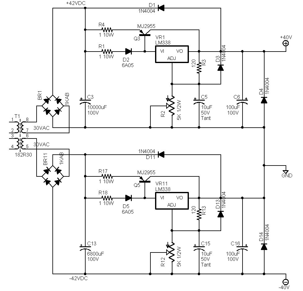
- Status
- Not open for further replies.
- Home
- Amplifiers
- Solid State
- SC480 Amp Questions