Learn from Errors Thanks You Ian Finch teaching>AGAIN
Sorry about the missing parts the testing circuit is within a load & signal input
Will it possible or still within an error?
Sorry about the missing parts the testing circuit is within a load & signal input
Will it possible or still within an error?
I'm not sure what you mean to say, briansune. Perhaps you are saying the amplifier is connected to a load (speakers?) and you have a signal source connected too?
For any tests here, where there are basic problems like shorts and semis failing, remove the input and outputs. Get the amplifier stable with correct bias current and low overall current draw from the power supply first. Then consider a load like speakers and a signal input.
Let's check the basic setting:-
Do you know how to measure and set the quiescent or idle current? You are looking to have just 25 mA flowing through the output stage from the emitter of the 2N3055 to the emitter of the MJ2955. You can also say it is the voltage across the output transistor emitter resistors. Across both resistors, the current will be the voltage divided by the total resistance. For example, you may have 2 x 0.22 ohm resistors and a total of 0.44 ohms, so you need to read 0.025 * 0.44 = 11mV across both resistors.
Can you measure and adjust it with the potentiometer? It is important to answer the questions so we know what is happening, so please try as simply as you can - no special words are necessary.
I have check the voltage across both resistor and the reading is about 18mV
And the transformer is 30-0-30 Vrms
by the reading of my meter the input voltage is only 20Vrms in both +ve side & -ve side
And the transformer is 30-0-30 Vrms
by the reading of my meter the input voltage is only 20Vrms in both +ve side & -ve side
Great! That's more acceptable current now. I see it was the AC supply you referred to. Now the DC will be around +/- 43V. It seems near correct otherwise and assuming you can adjust the bias/idle current easily enough to 25 mA, the amplifier will work with low power OK but because the voltage ratings of the power tramsistors are much exceeded, it will fail sooner or later unless your parts are verified as having actual Vceo > 80V.
For the sake of long life, reduce the power supply rails or change output transistors to genuine MJ15003/4 (There are many fake supplies) or similar. Better still. use modern plastic ones like the excellent 2SC5200/A1943 or their TO247 versions.They are quite cheap now and will have no voltage problems.
The next remaining problem is the VAS transistors. You could test Vceo with a high voltage supply and high value (say, 2-5 megohm) in series to limit current. The problem is, dissipation is higher on higher rails, so replace with BD139/40 which are the same as BC639/40 with a heat spreader in the bigger TO126 package. Still test for adequate Vceo or it's just more toasted parts. Otherwise, check Greg's listing of good, known parts.
As a general guide, old video driver transistors from CRT televisions are the preferred types for speed and low capacitance (Cob), You may have local supplies that are fine for the job. BF469/70 and similar types are excellent parts here.
Good luck this time 🙂
Last edited:
Will it be possible to replace BC640 into 2N4033 & BC639 into 2N3019?
I checked the data sheet is seems to be close in rating?
And there is one more question which is not understand< why a 30Vrms will drop into 20Vrms? with out any signal input and load<??
THANKS
I checked the data sheet is seems to be close in rating?
And there is one more question which is not understand< why a 30Vrms will drop into 20Vrms? with out any signal input and load<??
THANKS
First, with similar voltage ratings, the metal types will be OK too but with lower current capacity as well as the 80V Vceo, they will fail a bit too easily, though I haven't used them for over 30 years. Perhaps I have forgotten how tough these old parts can be?
The 30V AC is normally rectified to 43V volts DC, OK but here you have dynamic filament resistance in series with the AC supply of, say 220V, so the supply falls as the load increases and the bulb begins to glow, reducing the primary voltage even further. Since the secondary winding(s) supply a proportion of the primary voltage (set by the turns ratio), they will fall proportionally too. Thus the DC supply falls as the load.power increases. That is just Ohm's law in practice. In fact, any big resistor in the mains supply will show similar behaviour. Do you need to read up on these fundamentals or am I missing the point?
Measure the AC across the transformer primary with and without the bulb in circuit. It's not 220V is it? and so the DC supplied from the secondary windings will fall to 5 or 12 or 20V according to the current drawn by the amplifier. It's almost that simple.
We use a lightbulb because it's cheap and accessible even though it feeds only a fraction of the power that should be applied to a working amp, this is only to save toasting parts when errors are made - if you use a low rated incandescent bulb like 60W or less. When the amp appears to respond to set up procedure, then remove it and reset normally.
I hope I have understood the doubts underlying your question.
Last edited:
Uh?
PS
You are quoting VRMS for some DC readings which is confusing. Sure, DC will read on AC settings of a multimeter but with errors.
Be sure to set the meter to a correct Voltage type where it applies, like VDC after the rectifiers. VAC before.
PS
You are quoting VRMS for some DC readings which is confusing. Sure, DC will read on AC settings of a multimeter but with errors.
Be sure to set the meter to a correct Voltage type where it applies, like VDC after the rectifiers. VAC before.
oh Ian<
i just wanna keep sure it is normal cause the issue makes me feel there are so many things need to be sure or check.
For a vacuum tube amp normally it will only drop about 10Vdc to 20Vdc from a 300Vdc supply which you had said that it only depends on the loading.
For save, i just confirm the Vrms is in a normal level.
My transformer is about 300VA, in normal one of the side will only draw about 2.4A max. and in both side it will be about 4.8A to reduce the heat of the transformer, it is better to increase the power of it.
So when the testing goes wrong, i am quite afraid to burns out all the components.
REGARDS
OK, I think I understand - you see a big voltage drop and wonder how bad the remaining faults are?
You also said that you have only 20mA current flowing to the amplifier which is fine - so far. It suggests to me that the bulb will not be glowing at all and near full 220V AC will appear across the primary and your rail voltages should be close to 43V DC. If not, the fault is obviously not in the amplifier but the power supply, so you have a fault in the rectifier, main electrolytics, connections or the trafo itself.
Remove the amplifier and test the power supply output. If the output is not correct, you know what to do, surely. If it only drops with the amplifier connected, you need to learn how to use the meter when measuring current. Let's be certain of your measurements first.
ya Ian < i have checked the voltage from the transformer, and it show out that the voltage are both 43Vdc when across a 3k3 ohms resistor. So that mean the transformer is no down at all. But when i put in the amp, the voltage drop from 43Vdc into 20Vdc when it is no loading or signal input. and the current across the amp is about 1.2A which mean the sum of both sides is about 2.4A and the current across both 0.44 ohms resistor is still the same.
I'm too confused here, briansune. First you have replaced output transistors and say only 20 mA current is drawn, Now you are saying that 1.2 A is flowing! Actually, I can believe that, if your supply has fallen to +/-20VDC.
Unfortunately it has taken several posts for you to verify important voltages. We cannot assist without good information.
Now, some fundamentals:
How are you measuring this current?
When are you going to answer whether you can adjust the DC current with the bias potentiometer? Remember, the total current in the output stage flows from rail to rail, so it is only 1.2 amps, not both rail currents added to 2.4.
What happened to the small current flowing in ther output stage as you measured only 18mV across the redistors?
The DC current flowing in the output stage is set by the bias adjust potentiometer. If you have this set wrong or the transistor is not attached to the heatsink or one of the output transistors correctly, you will not be able to set it correctly. Do you understand this?
Finally, If you are making changes please tell us when posting more different results. It's impossible to know what your results mean when you keep changing figures.
Last edited:
Reply your first question <( First you have replaced output transistors and say only 20 mA current is drawn, Now you are saying that 1.2 A is flowing!)
The data of the 1.2A is checking the current passing into the amp but not the resistor( this data is checked by series the meter with the supply and the amp ), cause when i check the voltage from both 0.22 ohms resistor the voltage is about 18mV, which is quite a bit higher than you said. The use of the current is to check whether the total power dispose to the amp are acceptable or not.
I will try to fix the bias potentiometer cause i find out a problem in this part.
After that i will reply you as soon as possible!
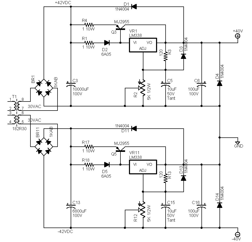
Hey Ian, after the checking, i think the better way to reduce more burning component in the future is adding a voltage step down regulator for example LM338K. The LM338K would easily turn the 43Vdc into 40 voltage which maximum rating will be 5A this is much enough for stereo amp.
What do you think if that possible or sweeping the 2n3055 is much better?
Case i am still thinking on some silly question such as my transformer is 300VA as i mention, and the rectifier for the SC480 amp is only using a 1N5404 which is in a maximum rating of 3A. So it is no possible to just use one rectifier to supply. But what's the point to make two rectifier for only one transformer?
Hi
Have you found the problem with the bias circuit yet? Just as important, have you found where the current path for this 1.2 amps is yet?
Since we know that only a few mA is flowing through the output transistors, a quick check of the schematic should reveal the only other options:
i.e. Driver transistors, VAS/bias circuit or the input stage. Since breaking circuits to test the current is not practical, it is good to measure the voltage drop across resistors in the circuit and to estimate current by calculation. Some mental arithmetic is quite useful here. When you have found where the current flows, you have your problem, OK?
Regarding regulators, these are certainly possible but three terminal types will likely need more than 5V drop to say, 38V rails. With a big trafo of 300VA, this will be OK most of the time but will cut out of regulation when the supply sags at high current. It is too close for practical use with rails set at much over 35V, I would think.
In sharp contrast, the SC480 design is an upgrade of an old but very cheap and popular kit (ETI 480) introduced by ETI Magazine in this country many years ago. It used small, 120VA trafos with small diodes as you still see and the supply voltage sagged under load (intentionally) to protect all the power transistors which otherwise would operate beyond their SOA (Safe Operating Area) limts.
It is now fashionable, but a bad idea to use oversize transformers, overkill capacitance and huge rectifiers on this and similar amplifier designs. If we must have big, stiff power supplies, then we need big stiff semis with plenty of excess ratings to match. This is the most sensible and economical way to match available standard trafos, if you can't afford a custom wound one of a more suitable power rating.
Seriously, the best, more efficient power supply is one that is unregulated but adequately filtered. To solve the high voltage problem, it is simpler to use modern, higher voltage audio transistors. I even have a personal note from the SC480 designer where he recommends this. suggesting MJL3281/1302 for Hi-Fi use, IIRC. The reason why the 2N3055/2955 are used here and in many similar, cheap utility amplifiers, is only for a low-priced kit. There is no other reason to use such slow and poor linearity transistors.
Having criticized them, I should admit that plenty of good designs have used them over 40 or more years but I hope we try to improve on these old standards now. We have already discussed the other power transistors for their limitations too.
I hope these suggestions are useful to you as we have no idea of your location yet, so I cannot really make specific suggestions.
Last edited:
YES finally the flux have short both +ve & -ve voltage in some of the point( first i am not sure cause the meter cannot check it out but after clean it with some solution and re-solder all the components it final drop into a steady current.) and it work well after adding the LM338K.
Good work, briansune. It takes determination to go back over our work - I don't like admitting to errors either but we all make them unless we are very experienced. Don't forget to set the bias current to 25 mA and check that it is stable over several hours.
It's a pity you need to use regulation of the rails. It is expensive and for proper regulation at full power, you lose the potential of the big transformer.
Anyway, I hope you enjoy the amplifier and take the first opportunity to try it with better components and full rail voltage. They sound much cleaner, believe me.
the design for the LM338K can also step up the voltage which means i can also try the MJ15003 & MJ 15004 Too thanks a lot Ian
Hey Ian by the time is checked the left sides of the amp i had made the right side. This time, there is one problem, which is the resistor of the 0.22 ohms can only draw about 1.3 mV which is the current is only about 1.2mA when no load and signal input.
So what do you think? There are problems in the bias?
So what do you think? There are problems in the bias?
Usually, we have the opposite problem - too much current. Let's see if we can find why.
You are right to suspect the bias circuit and fortunate to have a good amplifier for comparison.
First , check the temperature, by hand, of the VAS transistors. They should not be very hot or at least the same in each amplifier. Then measure all the B-E voltages, including the bias transistor, which should be about 0.6V. If this is not so, check rhat you have them the right way around. and the voltages across the resistors which are connected are the same (this is the same as current comparison and verifies DC conditions).
If the voltage amplifier stage (VAS) is OK, then check the driver transistor voltages to make sure there are no open circuits or failures there. No bias means no DC on their base, which should read about 1.3V, base to output, on both positive and negative drivers or 2.6V between bases. Next. the output transistors should have half this voltage, at O.6V or their normal B-E voltage. This DC bias is set by the generator, so don't forget to check that it works by adjusting it and resoldering in case of faults etc.
The design is such that if the bias adjust potentiometer fails with open circuit, bias will fall to zero for safety. This may be a clue.
Good hunting.
Hey Ian after checking all the bias of the transistor is quite good and finally it is measured the rate of 0.02A rail to rail. Which i think is normal, but the B-E voltage of the transistor is quite high in some place which is measured in 6.2 or 6.5V and the output push pull transistor is 5.8V which is a bit lower than it should. So what do you think?
- Status
- Not open for further replies.
- Home
- Amplifiers
- Solid State
- SC480 Amp Questions