Hi all.
I have constructed the Silicon Chip Nov 2012 Classic D amp.
The amp operates, producing clean sound. But at idle the temperature of the two IRFB5615 MOSFETs climbs steadily, reaching the 70 deg C protection trip.
Specs are:
B+/B-: +/- 50 V
VAA/VSS: +/- 5.6 V
oscillation frequency: 500 kHz
deadtime setpoint: 45 ns
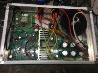
Enclosure layout is by me.
Attached are scope shots which I think illustrate the problem.
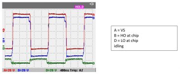
- Shot 1 shows VS/HO/LO at idle.
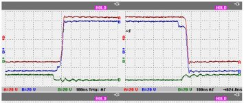
- Shot 2 zooms in a little, showing the glitches in the HO curve (curve B).
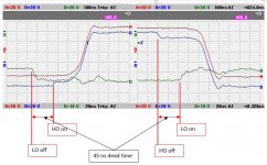
- Shot 3 zooms in further, showing the deadtime and the lag in HO turning off. When HO switches off, it stays high for 30-40 ns longer than the deadtime. For this period both HO and LO are on. There is a similar lag when HO switches on.
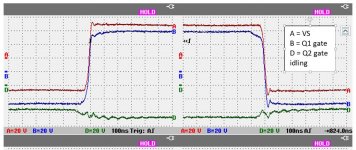
- Shot 4 shows voltages at the gates of the MOSFETs.
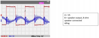
- Shot 5 shows VS and the output at the speaker connection.
So I think the overheating is caused by the brief period when both HO and LO are on. But I cannot see why this is happening.
I have already replaced the 2092, both 5615s, and the TIP31C. I have removed and checked all capacitors and resistors associated with the switching.
By now the design is mature, and I am sure that many have been successfully constructed, so I am puzzled by this!
Would appreciate any comments.
Thanks!
I have constructed the Silicon Chip Nov 2012 Classic D amp.
The amp operates, producing clean sound. But at idle the temperature of the two IRFB5615 MOSFETs climbs steadily, reaching the 70 deg C protection trip.
Specs are:
B+/B-: +/- 50 V
VAA/VSS: +/- 5.6 V
oscillation frequency: 500 kHz
deadtime setpoint: 45 ns
Enclosure layout is by me.
Attached are scope shots which I think illustrate the problem.
- Shot 1 shows VS/HO/LO at idle.
- Shot 2 zooms in a little, showing the glitches in the HO curve (curve B).
- Shot 3 zooms in further, showing the deadtime and the lag in HO turning off. When HO switches off, it stays high for 30-40 ns longer than the deadtime. For this period both HO and LO are on. There is a similar lag when HO switches on.
- Shot 4 shows voltages at the gates of the MOSFETs.
- Shot 5 shows VS and the output at the speaker connection.
So I think the overheating is caused by the brief period when both HO and LO are on. But I cannot see why this is happening.
I have already replaced the 2092, both 5615s, and the TIP31C. I have removed and checked all capacitors and resistors associated with the switching.
By now the design is mature, and I am sure that many have been successfully constructed, so I am puzzled by this!
Would appreciate any comments.
Thanks!
Attachments

The DT values are wrong.
4k7 should be 8k2 and 5k6 should be 3k3.
That is according to the data sheet and most commercially produced successful amplifiers.
4k7 should be 8k2 and 5k6 should be 3k3.
That is according to the data sheet and most commercially produced successful amplifiers.
This probably will not help but from one of your pictures, attached, A is VS. B is HO. Notice how B appears to hit a plateau and A only makes the transition sometime after D, LO makes its transition to high. However HO maintains its plateau for some time afterwards.
If you are at idle then your inductor current will/should be triangular. That means it is driven positive when HO is on. If HO turns off properly that net positive current should drive VS down as the inductor tries to maintain the flow and resets to the negative rail.
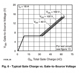
Based on the above it would appear that your upper Mosfet is not being turned off properly so you are seeing shoot through current. With your 20V/div it looks like the gate is sitting at 5V which is likely above the gate threshold voltage, VGSth.
As to why... ? For the moment I cannot think of a reason but the words seem to make sense. Is the 22R resistor still 22R. Try adding a 1n4148, bar to chip, across it to improve the turn off
Second picture is indicative of the plateau but that one is or should only be there when the device is making the transition, Miller Effect, due to dVDS/dt.
As an aside I assume the messy waveforms are a result of not using a short ground probe on your scope probe. You might find a springy thing in your bag of bits that goes on the shiny ring or you can solder a BNC to the board.
If you are at idle then your inductor current will/should be triangular. That means it is driven positive when HO is on. If HO turns off properly that net positive current should drive VS down as the inductor tries to maintain the flow and resets to the negative rail.
Based on the above it would appear that your upper Mosfet is not being turned off properly so you are seeing shoot through current. With your 20V/div it looks like the gate is sitting at 5V which is likely above the gate threshold voltage, VGSth.
As to why... ? For the moment I cannot think of a reason but the words seem to make sense. Is the 22R resistor still 22R. Try adding a 1n4148, bar to chip, across it to improve the turn off
Second picture is indicative of the plateau but that one is or should only be there when the device is making the transition, Miller Effect, due to dVDS/dt.
As an aside I assume the messy waveforms are a result of not using a short ground probe on your scope probe. You might find a springy thing in your bag of bits that goes on the shiny ring or you can solder a BNC to the board.
Attachments

Just in case. Possible slight correction due to finger waving. Perhaps the upper Mosfet is getting down to 0V VGS but once again if it is being properly switched off the inductor current should be driving the transition. It looks like LO is suffering from similar issues. When either device properly switches off I would expect VS to almost immediately make the transition before the opposite device is turned on.
The DT values are wrong.
4k7 should be 8k2 and 5k6 should be 3k3.
That is according to the data sheet and most commercially produced successful amplifiers.
Thanks Jon. The design write-up says the amp is based on mode DT2, which is 45 ns and requires the 5.6/4.7 arrgt. Nonetheless I will certainly try the 8.2/3.3 setup - it seems clear that the deadtime needs to be longer.
Just in case. Possible slight correction due to finger waving. Perhaps the upper Mosfet is getting down to 0V VGS but once again if it is being properly switched off the inductor current should be driving the transition. It looks like LO is suffering from similar issues. When either device properly switches off I would expect VS to almost immediately make the transition before the opposite device is turned on.
Thanks for your comments MF. I agree that VS needs to be following HO more closely. Just cannot see why its not happening.
Hi Jac2345,
I know its been a while since anything was posted about this issue but...
I have actually the exact same problem as you, its the center Mosfet that is overheating first and after double and triple checking I can't find the reason for it doing that.
Did you ever manage to figure out what the problem was and how to fix it?
I too seem to have suffered the same fate, although probably because of higher mains voltage at my house (252v - we are right next to the substation) mine didn't just warm up... It went bang!
I had just finished putting everything together, double and triple checked everything, set it up per instructions, checking all relevant supply voltages, set the idle switching speed trimpot, then finally powered it down, removed the setup jumper. Connected a 4 ohm dummy load resistor, no input signal though, and turned it back on, with the scope showing the VS output. It was switching at ~470khz. In the 20 seconds i was adjusting the scope to get a good look at the switching waveform, that's all it lasted until the fuses went BANG. Both mosfets shorted. The board is okay thankfully.
This only happened yesterday, last night I desoldered the mosfets. I'm going to try probing the gate drive signals with no fets in place later tonight, will also replace the IRS2092 for good measure. Will the IRS2092 be okay to probe with no fets in circuit? I know the bootstrap supply won't be quite at the right voltage, but apart from that, should this allow me to check and see whether the gate drive signals were okay? and maybe more dead time wouldn't be a bad thing - I'm only using it as a subwoofer amp anyways..
I thought I'd post my experience since it does seem other people are having issues.
I work in the electronics repair industry by trade, so I will provide further updates when I get to the bottom of this.
-KabAudio.
Hey Kabaudio, did you ever get it working?
I just finished building mine and plan on using it for a subwoofer, but i found the heatsink gets mega hot.
I tried the DT suggestions above but it didn't help.. Then I tried an equivalent voltage divider to get around 8.5V at DT , since the datasheet has a 12V supply and i have 14.6V for Vcc.
Anyways.. it'd be good to know if you got it working without getting so hot. I just blew some fuses.
The DT values are wrong.
4k7 should be 8k2 and 5k6 should be 3k3.
That is according to the data sheet and most commercially produced successful amplifiers.
On my 2092 design I just put 8k2 from DT to B-
This gives max deadtime.
I left out resistor to VCC out altogether.
I would also recommend 10R gate resistors on the mosfet to ensure fast switch on and off.
Hi I built this Jaycar kit and it has an overheating IRFB5615 Q1 which steadily climbs in idle mode with speaker attached, have checked values and voltages all check out ok according to the instructions, but still don't really know what could be causing it, the funny thing is I also built the same Altronics kit and it works fine without fault. does anyone have an idea what the fault could be?
Last edited:
- Home
- Amplifiers
- Class D
- SC Classic D - IRS2092/IRFB5615 - MOSFETs overheat at idle