Why are SB Acoustics published specs so far off?
Or is it me?
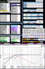
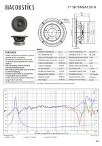
Pic 1, The alignment I was hoping to use based off the SB15NBAC30-8 Spec sheet.
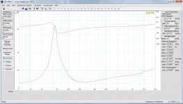
Pic 2, DATS V3 T/S results
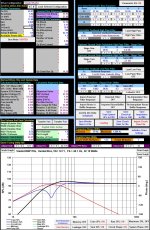
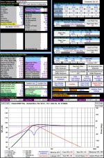
Pic 3, When I update the T/S parameters in Jeffs spreadsheet from the SB data sheet to the measured DATSs parameters, the alignment falls apart. The box will have to be at minimum twice as large as the spec sheet would suggest to get a decent alignment (Pic 4).
BTW, I *really* liked the alignment I had based on the spec sheet, hence why I bought the woofers.
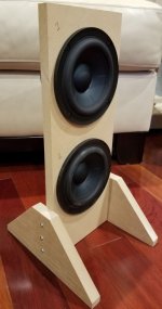
I built a little test stand to mount the woofers in a vertical position and keep the pole vents clear. Woofers were broken in with a 28Hz test tone at close to xmax for a couple of hours.
Any idea what I might be doing wrong?
Or is it me?
Pic 1, The alignment I was hoping to use based off the SB15NBAC30-8 Spec sheet.
Pic 2, DATS V3 T/S results
Pic 3, When I update the T/S parameters in Jeffs spreadsheet from the SB data sheet to the measured DATSs parameters, the alignment falls apart. The box will have to be at minimum twice as large as the spec sheet would suggest to get a decent alignment (Pic 4).
BTW, I *really* liked the alignment I had based on the spec sheet, hence why I bought the woofers.
I built a little test stand to mount the woofers in a vertical position and keep the pole vents clear. Woofers were broken in with a 28Hz test tone at close to xmax for a couple of hours.
Any idea what I might be doing wrong?
Attachments
SB's free air resonance is 35.5Hz and you are measuring 44 ish, that is quite a difference it may be that the surrounds need more breaking in which would lower the Fs. I think SB run their drivers for quite a while before they measure them.
Try breaking them in longer and see if the Fs continues to drop.
P.S 10Hz tones are good because you can't hear them but they easily get the surrounds moving.
Try breaking them in longer and see if the Fs continues to drop.
P.S 10Hz tones are good because you can't hear them but they easily get the surrounds moving.
You can't really repeat their measurements because you don't have exactly the same tool and you didn't use the same test conditions . And these conditions are very important. For example what was the voltage swing when the measurement was done. Was it an force current, measure voltage, or force voltage measure current. Was it 1V, 2V etc.
The DATS system is a very basic system. I have the the DATS 2. Many of the test conditions do not reflect operational conditions. The power of the DATS system is very small, possibly to the tune of 10mW whereas listening conditions are probably at a few watt.... I understand V3 can go higher but I don't think it is a few watts.
So, just understand the limitations and use it for what it is worth.
Oon
This is SB's process for measuring
https://sbacoustics.com/wp-content/uploads/2021/01/Measuring-Thiele-Small-parameters.pdf
Using ARTA or REW a simple impedance jig and reasonable quality headphone amp it should be easy enough to match SB's method.
Avoiding any walls or surfaces near by and still having the driver mounted vertically would need a different mounting method than shown in the image above. The baffle and proximity to the floor will load the driver somewhat and raise the Fs.
Hi,
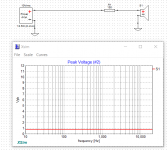
Interesting note. However there is something I like to point out which may not be clear. There is a 150 ohm resistor in series. And measurements is done with the voltage at the terminal at 1V rms at resonant frequency. Therefore the voltage at the output of the amplifier would probably be something to the tune of 5 to 10 times higher.
So.i think you would need a proper power amp to do this.
Can also be done with a hybrid oscilloscope/network analyser stuff which is quite cheap nowadays. Did that once, was trying to study how resonance frequency of port changes with power...
Oon
Hi,
And measurements is done with the voltage at the terminal at 1V rms at resonant frequency. Therefore the voltage at the output of the amplifier would probably be something to the tune of 5 to 10 times higher.
Oon
I think Constant Voltage source of 1 vrms, then 150ohm. So, Voltage at driver terminal will be less then 1V.
Thats how I understand this:
" We use a constant voltage source and a
150 Ω resistor in series with the drive unit"
Hi,The DATS system is a very basic system. I have the the DATS 2. Many of the test conditions do not reflect operational conditions. The power of the DATS system is very small, possibly to the tune of 10mW whereas listening conditions are probably at a few watt.... I understand V3 can go higher but I don't think it is a few watts.
Oon
How accurate is it if I amplifier the DAT2 output provide impedance match to input of the amp to drive the UUT? Amplifier with low distortion is preferred. Is it doable? I have DAT3. Thanks
I think Constant Voltage source of 1 vrms, then 150ohm. So, Voltage at driver terminal will be less then 1V.
Thats how I understand this:
" We use a constant voltage source and a
150 Ω resistor in series with the drive unit"
Further into the document : "The voltage that should be applied to the terminals of the drive unit
depends on its size/type. For a typical mid-woofer, the voltage should be about 1 V (rms)
at the resonance frequency"
Impedance measurements done with dats often looks ragged where they should not, i do not know if it is because of the user or the dats or both, but the short sweep used by dats does not look to be the best test stimuli for all drive units. And drive level seems to be very low, maybe so low that it is near the noise floor of the setup!? stepped sine or very slow swept sine seems to be the most accurate stimuli
Based on what I see in DATS 2, i can't say about DATs 3, has to do with the microphonicnature of the cone. It generates an EMF and that makes all the reading go haywire. I would be listening to music while working on it. Then I get all this weird readings, but it stops once I turned of the music. Happened a few times.
Oon
Oon
Not quite. I believe the measurements were taken at the point. I remember reading somewhere it is a voltage source with a 1kilohm resistor in series. Voltage is measured at the end of the resistor. So you can't quite connect to the amplifier like that. Would have been different if it was external.Hi,
How accurate is it if I amplifier the DAT2 output provide impedance match to input of the amp to drive the UUT? Amplifier with low distortion is preferred. Is it doable? I have DAT3. Thanks
I used a computer based network analyser/oscilloscope (cheap stuff about $100) to do it, . It has separate signal generator and extra probes.
Oon
- Home
- Loudspeakers
- Multi-Way
- SB15NBAC30-8 Spec sheet way off?