Hi,
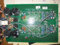
I am trying to set the bias on two musical fidelity xas100 power amps (4 mono amps).
Chips used are SAP15.
Datasheet has an explanation, as do sites/forums online but I'm struggling to interpret the information and apply it to the amp. I'd say my knowledge is begginer.
Data sheet:
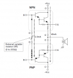
"1. Recommended Operating Conditions
➀Add a variable resistor (VR) between diode terminals to adjust the idling current. The
resistor having 0 to 200Ω is to be used.
➁Adjust the forward current flowing over the diodes at 2.5mA.
➂Adjust the idling current at 40mA with the external variable resistor.
Both the temperature coefficients for the transistor and the diodes are matched"
200 Ohm VR fitted between (D-D)
Assuming the 2.5mA will be set by design (across D -D)
All I need to do is adjust the idling current to 40mA Question is, where do I take readings from to determine the current?
Any advice/assistance is much appreciated.
Thanks,
Kevin
I am trying to set the bias on two musical fidelity xas100 power amps (4 mono amps).
Chips used are SAP15.
Datasheet has an explanation, as do sites/forums online but I'm struggling to interpret the information and apply it to the amp. I'd say my knowledge is begginer.
Data sheet:
"1. Recommended Operating Conditions
➀Add a variable resistor (VR) between diode terminals to adjust the idling current. The
resistor having 0 to 200Ω is to be used.
➁Adjust the forward current flowing over the diodes at 2.5mA.
➂Adjust the idling current at 40mA with the external variable resistor.
Both the temperature coefficients for the transistor and the diodes are matched"
200 Ohm VR fitted between (D-D)
Assuming the 2.5mA will be set by design (across D -D)
All I need to do is adjust the idling current to 40mA Question is, where do I take readings from to determine the current?
Any advice/assistance is much appreciated.
Thanks,
Kevin
Attachments

Thanks for the info, much appreciated.
I have set the (first after the VR) SAP15 NPN side across pins 4+5 (S+E) to 8.8mv on all 4 amps.
Measuring the DC across the speaker terminals shows varying amounts on each amp. Also, now that they have been on for 30mins and settled each heatsink is the same temperature at 40deg C. All emitter R now measure 9.6R.
Amp 1: 30mV
Amp 2: 3mV
Amp 3: 21mV
Amp 4: 52mV
Should I be concerned about the differing DC voltage at the output?
Thanks
Nothing wrong here all amps, without servos at least, have a bit of offset. under 100mV is not a danger to speakers.
Bit of a thread revival, but thanks for the helpful info in this thread.
When you set the idling current did you check the voltage drop across the emitter resistor on each transistor and if so which one did you use as your reference for adjustment?
The voltage varies across each emitter resistor and there is also a small variation in actual emitter resistor values, maximum in my case was -0R02. I took this into consideration, calculated target voltage drop for each emitter resistor and then adjusted idling current to match. I was able to get within -0.5 +2mA of the target Ic for three of the four SAP15's in my MF A308, with one SAP15PY on left and right channel being high (albeit a lot lower than pre-adjustment). Did you see similar results?
I measured with load connected as indicated in the datasheet.
- Home
- Amplifiers
- Solid State
- Sap15 biasing in power amp