Hy everyone!
I have a Sansui Tu9900 and wanted to upgrade the Opamps from the old ta7136p to new Opa604. The upgrade is well described in many places (Tuner Information Center - Jim and Bob's DIY Mods). I have followed this instructions but the tuner is not working. I double checked the connections and they should be fine (pins 2 and 3 are inverted, 1 and 5 not connected, positive voltage on 7, negative on 4). I see with the scope a signal coming in in pin number 2 but nothing coming out of pin number 6. The only thing that is not how it should be is that I get a positive dc voltage out of pin 6 (+12v to be precise).
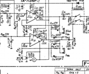
I have attached the schematics od the radio and the data sheets of both opamps.
Somebody is able to help me?
Thank you very much!
I have a Sansui Tu9900 and wanted to upgrade the Opamps from the old ta7136p to new Opa604. The upgrade is well described in many places (Tuner Information Center - Jim and Bob's DIY Mods). I have followed this instructions but the tuner is not working. I double checked the connections and they should be fine (pins 2 and 3 are inverted, 1 and 5 not connected, positive voltage on 7, negative on 4). I see with the scope a signal coming in in pin number 2 but nothing coming out of pin number 6. The only thing that is not how it should be is that I get a positive dc voltage out of pin 6 (+12v to be precise).
I have attached the schematics od the radio and the data sheets of both opamps.
Somebody is able to help me?
Thank you very much!
Attachments
I can see no reason why this wouldn't work as long as you have done as you mention. Pins 2 and 3 swapped and no connections to pins 1,5 and 8 of the OPA604.
What is the voltage on pin 2 of the OPA ?
What is the voltage on pin 3 of the OPA ?
They should be the same, and should both be zero (which they won't be given the fault)
Could the op amp be fake ?
What is the voltage on pin 2 of the OPA ?
What is the voltage on pin 3 of the OPA ?
They should be the same, and should both be zero (which they won't be given the fault)
Could the op amp be fake ?
Yes, pins 2 and 3 are swapped. Pin 8 is not connected. Pins 1 and 5 are phisically connected but I removed the resistors and capacitors tha were making the connections in the pcb. I get no dc voltage on pin 2 and 3. On pin 2 (pin 3 on the new opa) i see a signal coming sito the scope, nothing on pin 3 (pin 2 on the new opa). The only thing that is strange is the positive 12 voltage on pin 6. On the instructions that I posted they were saying that you can remove the last decoupling capacitor and have direct coupling since the re should be no dc current. I bought the opamps in at my local dealer so I don't think they are fake. Maybe defective?
Those DC voltages show a problem. If you have 12 volts on the output (pin 6) then that voltage should also be on pin 2 via the 47 k feedback resistor. Yes 🙂
So it sounds like some print is open somewhere.
So it sounds like some print is open somewhere.
It has to be something like that. The FET inputs of the opamp draw no current... so where has the voltage gone 😉
I have checked again the voltages. I made a mistake before because I reported the voltages without the opamp in place (my notes where a bit confused, sorry for that). Anyway a get ~0,5 volts dc on pin 2 (negative input, pin 3 on the old opamp), 0 volts dc on positive input, 12 volts dc on the output, and +12 on pin1 and -12 on pin 5 but those are coming from the opamp because the moment I disconnect it I get 0 volts from both pins on the pcb.
No problem 🙂
Lets look at what you have got... and all voltage are to be measure on the actual pins of the OPA604 (otherwise it gets confusing)
Whatever voltage is on pin 6 should appear on pin 2. Look at the circuit. That voltage couples through the 47k feedback resistor. Under fault conditions there is a little problem though, the two electrolytics that are the feedback return (those under the opamp) are reverse biased if the opamp output is + 12 volts and so they could leak drastically and affect readings.
However, if the 47k is really connecting pin 2 to pin 6 of the opamp, then this should not be happening.
This can only be either a fault with the way you have it wired or a fault with the opamps. Any opamp will work to prove that, even a 741 or TL071.
Attachments
On the guide it was written to remove the two caps (c5 and c6) and replace them with a jumper Wire. I actually tried with the jumper, the capacitor and just leave it unconnected and in none of these combinations did it work.
It sounds like there is a problem with your opamps tbh. Its a basic text book opamp configuration with a feedback resistor and gain setting resistor.
The links across the caps should not affect the overall result, but they will affect voltages in fault-finding if the caps are linked. With no cap and no link the opamp could become unstable and give all sorts of odd voltages.
Try a different opamp type for one of them and see if it fixes it.
The links across the caps should not affect the overall result, but they will affect voltages in fault-finding if the caps are linked. With no cap and no link the opamp could become unstable and give all sorts of odd voltages.
Try a different opamp type for one of them and see if it fixes it.
Ok. Thank you very much. Ill try with a different opamp. Eventually could there be a defect somewhere else in the circuit that is interfering with the functioning of the opamps?
Sorry for the questions. I'm only an amateur and this is the first time I work with solid state. Thanks!
Sorry for the questions. I'm only an amateur and this is the first time I work with solid state. Thanks!
If it was working before then I can't see there being any other problem.
It has to be either the opamps that are faulty or something you have done incorrectly in swapping the pins around.
It has to be either the opamps that are faulty or something you have done incorrectly in swapping the pins around.
Problem solved. I changed the opamps and now everything is working... apparently they were defective or I ruined them somewhere during the assembly.
- Status
- Not open for further replies.
- Home
- Source & Line
- Analogue Source
- Sansui Tu9900 Ic upgrade