Yes the FM IF filter is easy for me to see, the "AM" If filtering was confusing, thx for the explanation.
I was working on a balun for the AM antenna too. Used a biconic(two holes) ferrite, from Amidon, as suggested by Burkard Kainka, using about 5-6 strands of litz wire. I wound the secondary for the required L for the Si4735 spec.
See:
DSPradio
Using Google translate in a Chrome web browser.
I was working on a balun for the AM antenna too. Used a biconic(two holes) ferrite, from Amidon, as suggested by Burkard Kainka, using about 5-6 strands of litz wire. I wound the secondary for the required L for the Si4735 spec.
See:
DSPradio
Using Google translate in a Chrome web browser.
If you haven't already check out fmtunerinfo, Tuner Information Center - Vintage Stereo Tuners usually provides troubleshooting and mod advice.
@Rif: I have. Good source, though.
@Tico: My issue is with AM performance. There's a lot to be gained here. The PSU, while late seventies in design, won't make one iota of difference in this area.
@Tico: My issue is with AM performance. There's a lot to be gained here. The PSU, while late seventies in design, won't make one iota of difference in this area.
The AM sucks big time.🙁
Depends what you are after.
AM is a problem, especially here in North America, where number of stations are on the same frequency.
In the day time that's not a problem, but at night it is. So forget the long wire antenna, you will need a directional one, a loop antenna, ferrite or air core, other wise you would receive more than one station at the same time.
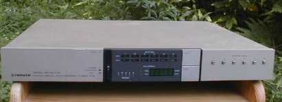
Among the "super tuners" I only know one which has a decent AM section, with IF band width switching and that is the not so impressive looking Pioneer F9 from the early eighties. Here is the schematic of the RF/IF section. It also have a very good FM front end.
Attachments


I guess it called Philips as you stated, it's always a better one around.
Most Grundig portable radio's have a better one to, etc etc
Most Grundig portable radio's have a better one to, etc etc
Oops, I'm sorry, I just realized you are in the Netherlands, not in North America, so the loop thing is not apply to you.
Well, my goal is to get transatlantic DX. For that I definitely need a narrow IF. The beat canceler feature with the synchronous demodulator will help with co-channel interference from the different frequency spacings (9 vs. 10 kHz). Since many MW transmitters are being switched off here in Europe DX should become easier.
A shielded loop antenna is a very relevant option over a long wire. Anything to get rid of the noise cloud... But first must find a suitable IF filter for 455 kHz...
Pioneer F9 is a nice radio, but no synchronous detector. Or maybe it has, the schematic I found is a bit incomplete. Mind you, there were tube radios with one, Körting Syntector comes to mind. Would be nice in my collection 😀
Last edited:
First off, RF AGC is a Good Thing[tm]. The TU-X1's two RF preamps would certainly have tended to overload the poor mixer very quickly otherwise. In addition, Japanese tuners in particular tend to have rather nonlinear IF strips, with limiting occurring early on. (A limiter is, after all, a nonlinearity by definition.) I suppose this gives better quieting and capture ratio, but at the cost of worsened selectivity at higher signal level, due to the IMD generated. This probably was a reasonable choice for Japan, with relatively few, widely-spaced stations at the time. (It also means you can save power due to well-controlled signal levels.) In the crowded European band, however, it's not ideal.
You may have noticed that, on paper, the filters even in a typical midrange tuner ought to give some kick-*** selectivity if you just multiply their responses. In practice, it usually isn't like that - guess why.
I have seen very few tuner schematics with a truly textbook-level FM IF chain - i.e. keep things as linear as possible throughout the filter section and concentrate all the limiting at the end. One was the REL Precedent, an old professional American tuner, the other was a Revox A76 (I haven't seen docs for any other Revox though). If memory serves, the latter also used RF AGC, while the former employed manual gain control.
There is little you can do about signal strength indication accuracy here. Output is inevitably going to be compressed in the range of RF AGC kicking in. One could probably do some fancier things with the signal strength voltage these days and achieve better calibration, though I reckon a thorough realignment of the frontend would be required before variation across the whole band drops to a few dB.
On to the AM side of things:
Generally speaking, a fixed unbalanced wire antenna is about the last thing you want for AM DX. Unless your idea of DX is hearing all the switching power supply crap of the entire neighborhood, of course. In order to keep all the common-mode crap out, a self-contained antenna that does not rely on ground is required. Since on MW even a shortened dipole becomes quite unwieldy, a nice big (limits given by handling) tuned loop is pretty much the way to go. This is always good for inductive coupling to ferrite rods... well, maybe not always, some tuned ones may act up. On the loop, use only as many turns as needed for band coverage, and bigger spacing is better. Wire of a certain thickness is good, RF Litz wire even better. Keep wires well away from the floor, and in case of a square loop best make a stand so it can be rotated by 45°. The tuning cap should be an old-fashioned air varicap, best with two (near-)identical sections that can be put in series so as to avoid going through those pesky ground wipers.
TA DX tends to benefit from tight selectivity (which I kinda doubt in case of the TU-X1), synchronous detection, a quiet location near the sea (which may be quite feasible up there in .nl), and a good antenna in the right direction. I imagine a good Si4735-based portable coupled to at least a Tecsun AN-200 loop (though something a tad bigger does not hurt) should give fairly nice results already when given a good location. A loop will give some horizontal directivity and allow tuning out locals, vertically most everything that you string will be a blob facing upwards since you're too close to the surface (lambda/2 at 1 MHz is a pretty high tower). If you want more of those low incident angles, you'd have to string almost a km worth of longwire, plus whatever you need to interface the thing to your receiver (sounds like more of a job for a comms rx in this case).
Last edited:
AM will definitely be a challenge, as I'm smack in the middle of the city. Looks like I'll end up with a shielded loop antenna on the roof with a remote tuning capacitor. Just got a lovely RFT unit (NOS), you must be familiar with that brand...
As for the FM IF, the wide LC filter chain is divided between the limiters but the narrow SAW filter is all the way at the beginning, before any limiting. I guess the Japanese engineers followed your train of thought regarding the number of stations. Here in Amsterdam it's really crowded but even so the wide filter gives good results with the strong stations. My lovely Revox A720 (nixies!) has a seven section LC filter before any limiting is done. It also has no RF AGC whatsoever (respect!), even with no less than three stages of RF ampification. But it also uses a high level mixer which the Sansui lacks.
As for the FM IF, the wide LC filter chain is divided between the limiters but the narrow SAW filter is all the way at the beginning, before any limiting. I guess the Japanese engineers followed your train of thought regarding the number of stations. Here in Amsterdam it's really crowded but even so the wide filter gives good results with the strong stations. My lovely Revox A720 (nixies!) has a seven section LC filter before any limiting is done. It also has no RF AGC whatsoever (respect!), even with no less than three stages of RF ampification. But it also uses a high level mixer which the Sansui lacks.
Last edited:
- Status
- Not open for further replies.
- Home
- Amplifiers
- Solid State
- Sansui TU-X1 Modding