Having problems with AU-317 protection circuit. I have 12.5 volts on the collector of TR606 / TR607 when I should have 1.5V according to schematic
I've change D610 and all transistors with no joy. Also TR607 is running hot to touch but this could be normal.
TR605 collector and TR606 base I see 1.5V as per schematic, DC offset is to near as 0V as possible for both channels and Bias is 13mV for both channels. Sometimes it works normal but it depends on the temperature of the room as when the room is warm I see a big enough voltage potential drop across D610 which provides just enough voltage to activate relay (12V). If I had 1.5v on TR606/7 collectors the potential voltage drop would be around 22 volts which is what I would expect suited as the relay is 24V rated. I have recapped the amp completely and it sounds fantastic. I just cant get this part working. I am baffled and could do with an expert.
No dry joints etc. Someone please help 😕
Attachments
Last edited:
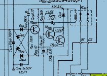
I would check the D611 thru D614 germanium diodes. If these are failing they may cause fits with the protection circuit even though the DC offset is measuring fine.
Thanks for you reply jhjove. I have tested them 1n34a diodes good on my Peak atlas tester. I even bought some new ones which were physically smaller and tried them with no joy. I have also changed the two Bipolar Caps
I think you have to go over the driver stage then, something there is providing an imbalance.
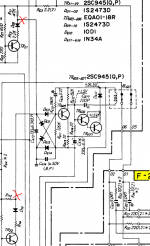
Possibly IC01, IC02 (2 FET devices in one package), bad device or solder connections or some other component failing around these?
Possibly IC01, IC02 (2 FET devices in one package), bad device or solder connections or some other component failing around these?
When I got the amp it was full of issues. I have sucked out all the old solder and re-soldered every connection with leaded solder. Just wondering if there was some sort on imbalance coming from the main amp section I could isolate the input to the protection circuit. No input would means TR05 would be turned off for sure and the protection relay should activate. I could put back just the the left channel then the right channel to see if just one side causes the issue. What are you thoughts on this ?
Attachments
Isolating a channel is a good idea.
Other components to check are zeners and non-flammable resistors. Have you gone through the driver/amp stage and just do ohmic measurements on the resistors? Check the zener voltages to verify they are in spec?
There's a good thread on audiokarma about these sansui non-flammable + fuse resistors, give a read may help you.
Wow I've never heard of a fuse resistor before and looking at the audiokarma examples to what they look like I see many of them in this amplifier. I have plenty of things to check now but never enough time lol. Many thanks again for your help and your interest in my issue. I will update after my next round of checks.
JHJOVE I can confirm that the issue is now fixed. I was reading the diagram wrongly so some of the stuff I mention in my 1st post is rubbish lol. Anyway I change all 4 Germanium DIODE 1N34A DO-7 which you did recommend and this has fixed it for sure. The weird thing is that the old diodes did past my "Peak atlas tester" I did also try replacing them with IN34A but they where not the type DO7 package. Any I have learnt loads and its all good experience.
Anyway I want to thank you for taking your time in helping me. Much appreciated
Anyway I want to thank you for taking your time in helping me. Much appreciated
I guess your were able to get germanium diodes. For the purpose of this circuit in the AU-317, I think schottky diodes may work as well.
The voltage drop across the PN junction of a schottky is similar value to a germanium but the schottky switches faster.
Glad you were able to repair the protection circuit.
The voltage drop across the PN junction of a schottky is similar value to a germanium but the schottky switches faster.
Glad you were able to repair the protection circuit.
- Home
- Amplifiers
- Solid State
- Sansui AU317 Protection circuit issue