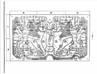
Hi. I have read the forum and service manuals and so on...
One channel died after I recapped the amp. I was very careful but now one channel is totally dead. I thought it was a fuse or a bad solder but I started to measure and I noticed there is no power at all from one of the channel from the PSU?! Should it be like that or what could have gone wrong? I'm not that "familiar" with reading schematics ... See the pix attached.
Thanks in advance.
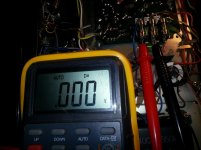
An externally hosted image should be here but it was not working when we last tested it.
Attachments
I don't think measuring voltage between fuses will tell us much without knowing what you are trying to tell us there. F002 and F003 are the respective V+ (56V) supplies to either amplifier. You measure the voltage on either side of the fuse to compare the voltage into and out with respect to ground - i.e the neg. lead touching ground. I guess you are saying that one fuse is blown and that channel no longer works? If so, measure the voltage between the supply and amplifier ground, since this is a single supply design and has capacitor output.
The question remains as to what changed values, types and polarity you recapped your amp with and whether modern, larger and low ESR caps simply caused a larger current inrush at start-up, blowing a fuse. A common mistake for unsuspecting new DIYs.
Posting a clear schematic or link to a service manual is good start if you expect others to help:
Sansui AU-555 | Owners/Service Manuals, Schematics, Free Download, Reviews | HiFi Engine
Hi,
Did you check the fuses for open? With the meter selector switch in resistance check both end of the fuses. They should read zero ohms resistance.
Did you check the fuses for open? With the meter selector switch in resistance check both end of the fuses. They should read zero ohms resistance.
Hi,
I downloaded the 555a squematics and those fuses in the pics look like to be an add on as they don't exist either in diagrams or pictures in the service manual.
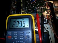
Also, 2.3V is not a voltage to consider coming from the PS.
If you are lost you should start taking measurements right at transformer input (input AC), then at the transformer output (output AC), then after the rectifier diodes right at the filter caps positive terminal against ground. That will tell if the PS is really working. The 555a PS is really a basic one and you should find this task easy.
Please report back so we can go on from your readings.
I downloaded the 555a squematics and those fuses in the pics look like to be an add on as they don't exist either in diagrams or pictures in the service manual.
Also, 2.3V is not a voltage to consider coming from the PS.
If you are lost you should start taking measurements right at transformer input (input AC), then at the transformer output (output AC), then after the rectifier diodes right at the filter caps positive terminal against ground. That will tell if the PS is really working. The 555a PS is really a basic one and you should find this task easy.
Please report back so we can go on from your readings.
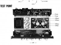
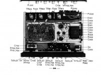
The fuses are positioned between the power transistors on both 555 and 555A models shown in the service manuals, sextaafondo. However, who knows if mods were required for a model sold over 40 years ago in Sweden, perhaps.
We only need to identy F001 (230VAC) F002 (56VDC left channel output stage) and F003 (56VDC right channel output stage) to find out whether power is available though. Note that an unfused 55V supply is always connected to the rest of the amp. and should always be available for checking, assuming that is not actually the third fuse we see in the pic of this amplifier. ! 😉
We only need to identy F001 (230VAC) F002 (56VDC left channel output stage) and F003 (56VDC right channel output stage) to find out whether power is available though. Note that an unfused 55V supply is always connected to the rest of the amp. and should always be available for checking, assuming that is not actually the third fuse we see in the pic of this amplifier. ! 😉
Thanks for all help!
I will try some of your hints tonight.
I'm pretty much a newbie so what I wanted to validate is that I had no power on one of the cables coming out from the PS and I find that odd...
So do you guys mean that this fuse holder is a "addon" ? I think it was sold in Sweden but it should have been untouched until I started to recap it.
I didn't messure the fuses but I swapped them left/right and so on and same result so the fuses are ok.
Ian and sextaafondo... Where do I put the multimeter to check this 😛 Do I need to open the PS ? Or are there spots I can messure. I can see F002 and F003 but not F001 ... Not sure where to put the multimeter ? Sorry but I need to learn (and ask to learn) =)
Thanks again guys! you really rock!
Just did some new measuring. What I found strange is that C002 and C004 have so different values ?
C819 and C820 = 29.18 and 29.87 V
C001 = 60 V
C002 = 44.8 V
C004 = 25.75 V
C003 = 29.90 V
F002 = 60.8 V
F003 = 60.8 V
All fuses are 0 ohm
Hope someone can give me some other hint here.
Thanks
C819 and C820 = 29.18 and 29.87 V
C001 = 60 V
C002 = 44.8 V
C004 = 25.75 V
C003 = 29.90 V
F002 = 60.8 V
F003 = 60.8 V
All fuses are 0 ohm
Hope someone can give me some other hint here.
Thanks
Last edited:
Those measurements are OK and say that the PS is working and IMO are within what would be expected though a bit on the high side. Might be due to the AC line being a little high, or due to the power amplifier not draining any current.
It's expected that voltage readings over C002 and C004 are different. Check out the PS desing. There are resistors separating them to provide different PS values.
Ian, and Evilution, regarding those fuses the stock ones as said should be located between the power transistors. The fuses in the first post pic are for sure some sort of repair job on the amplifier. Screenshots from the service manual below.
Some questions now:
Are both channels down, or is sound being amplified normally on one of them?
Have you chequed fuses after removing them from the fuse holders?
Have you got the squematics? In case you don't I attached a copy.
Attachments
Thanks for your replay sextaafondo. Good to hear all voltage are under "control".
Odd. Then I guess its a repair work or Swedish "law" addon... Not sure what it does thou. But strange there are no volt at all on one of the connections?
One channel is totally dead and one is working perfect. Same issue running through speaker A/B and headphones. Fuses have been checked removed and I also switched them left/right.
I got the schematics but this problem is "strange" and I'm not the best to read schematics either ... not sure "what I should be looking for" if you know what I mean ... Could one of the replaced cap be bad and cause this ? A wire loose somewhere ? Don't get it as one channel is dead through the (speaker terminals + phones).
Thanks again, I really appreciate the time you put into my issue here!
There is a fourth fuse for the 6.3 VAC to the pilot lamp. That will not show a reading on a DC scale and though I doubt this is located on the amplifier board, who knows with this extra board? Use a safe AC range to be certain but do not attempt to measure mains AC voltage unless your meter is marked as rated cat. II or better. Hobby DMMs are not and some just burn out on mains AC. Multimeter - Wikipedia, the free encyclopedia.
If this still fails to show a reading, trace the wire supplying the fuse back to its source and find where the power is apparently coming from. Actually, all power to the amplifier comes from the same source, same transformer, same rectifiers etc. The only difference is a few resistors limiting the current to the rest of the amplifiers and any fuses isolating each channel's output stage, as you see.
So , trace the source back by looking, following the schematic and any labels such as B1,B2,B3 etc. which identify the different supplies to the circuit sections I have just discussed. This is pretty self-explanatory when you have the schematic in front of you. Otherwise, you will soon get lost. 🙁
A test on the amps:
Having one good channel is a great advantage. You can compare key voltages between channels to locate fault areas for closer investigation. Look at the schematic's lower channel and see the expected voltages marked already. Now, locate the output capacitors C819, 820 then measure the voltage at the + terminal of these. Make sure your reference point for the -ve probe is always Power Supply ground. To avoid slipping with probes and blowing components it is smart to use a clip lead or probe tip to make the ground connection and then concentrate on safety with using just the other probe.
FWIW, inexperienced people often have this problem - they don't realise how fast and silently their precious components are smoked when they start poking around with meter probes or a screwdiver.
Thanks for your kind help and answers. I will go over the amp one more time asap.
Just a stupid question.... As the amp work fine before I recapped it ... Could a bad solder joint or a capacitor cause this issue ? Thinking if I should go back to the old ones to locate the issue that way ... I haven't touched anything else since this problem accrued so I'm a bit confused why something else than the capacitors should cause the issue ?
Thanks
It is indeed likely that you goofed somewhere, maybe accidentally creating a solder bridge or missing a solder joint.
Is there still some hiss coming out of the speaker on the dead channel? If so, does it change with volume or is it influenced by the tone controls?
Is there still some hiss coming out of the speaker on the dead channel? If so, does it change with volume or is it influenced by the tone controls?
Yeah I guess I have goofed somewhere... I was so careful but sometimes that doesn't help...
Nope, the channel is dead and there is not even a decibel coming out from it no matter what I change on the knobs .... No sound in the phones or speaker terminals ...
Nope, the channel is dead and there is not even a decibel coming out from it no matter what I change on the knobs .... No sound in the phones or speaker terminals ...
Yeah I guess I have goofed somewhere... I was so careful but sometimes that doesn't help...
Nope, the channel is dead and there is not even a decibel coming out from it no matter what I change on the knobs .... No sound in the phones or speaker terminals ...
Most likey you soldered one of the power supply wires in the wrong place. As a first attempt, follow the wires going out of the PS caps and trace them closely to where they go on both channels.
As the amp has 2 channels and one of them is working fine check out one channel wiring against the other. Must be simetrical, in other words a PS wire going to a certain point in one channel must go to the same exact point in the other. Do this with the amp OFF. Be very observant.
Most likely it's not the new caps in the PS as they feed both channels, and you have one running one.
Ian Finch: Yes indeed. Just afraid to measure on the wrong place and get a "kaboom" but I will go on the places I know is "safe for me" to start with.
sextaafondo: Great idea and I think this is the way to start somehow ... I must have messed up somewhere somehow. Will try your tip too.
Thanks again guys. If you come up with more ideas you're welcome to post. And/or whatever I'll get back as soon I have time to try some new things and tell you how it turns out. A cold beer from Sweden to you all 😀
So how about taking the voltage measurement(s)?
At least the PS voltage values were taken and posted in post #7. They look like to be within range.
True, we have the power supply voltages but only the rail supplies are measured at the amplifier. The quickest, easiest way to find if the amplifier is likely to function is to look at the DC level of the output node. That is, before the output caps, at their + terminals.
That has to be quick and simple and as the OP has already replaced the caps, I imagine he knows how to find them again and how to identify which terminal is +ve and where a ground point is.
That has to be quick and simple and as the OP has already replaced the caps, I imagine he knows how to find them again and how to identify which terminal is +ve and where a ground point is.
You are absolutely right.
Still, I'm not quite sure as to which caps Evilution replaced though.. PS caps, output caps... or all of them. Lets hear what he tells us.
Still, I'm not quite sure as to which caps Evilution replaced though.. PS caps, output caps... or all of them. Lets hear what he tells us.
- Status
- Not open for further replies.
- Home
- Amplifiers
- Solid State
- Sansui AU 555a One dead channel ? No power ?