Yes - I Checked the Pinouts: [According to the Letters on the F-2583 Board]
Pin1: E
Pin2: B
Pin3: (Not Labeled) [C, I assume]
Pin1: E
Pin2: B
Pin3: (Not Labeled) [C, I assume]
Whats over heating,the output transistors? Is it all of them getting hot? If so make sure you have the posistors (thermal sensors on the output transistors) plugged in? They should measure about 90 ohms. Take out the 2SA818s and test them and if you have the VD1212 diode D05 and D06 check them to see if they have failed? If so replace with 2 x 1N4148 small signal diodes soldered together in series.Check all the diodes and the current limiter circuit TR11,12,13,and 14.
Both the Brand New MJ21194 & 93's (the Right Channel is warmer), and most of the entire F-2583 Bias Board.
*I measured the Heat Sensors via the Leads, after removing the Plugs.
The Left Channel's Sensor reads 142Ω, and the Right Channel's Sensor reads 160Ω.
The Left Channel's Sensor reads 142Ω, and the Right Channel's Sensor reads 160Ω.
**The MJ2119x's Heatsink doesn't feel super hot, just warmer than it should. And it only takes 5-8 minutes. But the entire Bias Board [F-2583] seems to be about as warm.
That sounds about right. Ive got replacement posistors because this amp didnt have any when I got it. I think the originals are yellow?*I measured the Heat Sensors via the Leads, after removing the Plugs.
The Left Channel's Sensor reads 142Ω, and the Right Channel's Sensor reads 160Ω.
The amplifier is likely oscillating and consequently overheating. Check the Zobel network for damage- particularly the 4.7 and 10 ohm resistors- if they are blackened or heat affected, you have oscillation and need to fix it ASAP.
Check for HF instability, any and all compensation caps and you will need to consider slowing down the driver stage to allow for the replacement low fT output transistors you have used. You cannot have a front end and drivers that are faster than the output stage.
Kenwood L07m and L07mII use the same RET Sankens and are very sensitive to MJxxxx 'equivalents' being used. They love to oscillate and destroy themselves too. Ask me how I know that... 🙂
Bottom line is this, the On-Semi trs are not even remotely close to the originals, not in fT and not in particular, with gain at the ICs we are talking about.
Ive never heard of any complaints from using them? The reason Im using the MJ21193/94 transistors is because everyone else thats uses them says they are great! An expert on these vintage amps told me the outputs have little to do with improving sound quality. Ill have a good listen and decide if I go back to the original outputs or use MJ15024/25,Ive used them before and they sounded really good.The amplifier is likely oscillating and consequently overheating. Check the Zobel network for damage- particularly the 4.7 and 10 ohm resistors- if they are blackened or heat affected, you have oscillation and need to fix it ASAP.
Check for HF instability, any and all compensation caps and you will need to consider slowing down the driver stage to allow for the replacement low fT output transistors you have used. You cannot have a front end and drivers that are faster than the output stage.
Kenwood L07m and L07mII use the same RET Sankens and are very sensitive to MJxxxx 'equivalents' being used. They love to oscillate and destroy themselves too. Ask me how I know that... 🙂
Bottom line is this, the On-Semi trs are not even remotely close to the originals, not in fT and not in particular, with gain at the ICs we are talking about.
There is only one reason people use the MJ devices - there are no other options. They aren't suitable to use in most japanese designs, but again, it's all we've got. Sad but true.
There is only one reason people use the MJ devices - there are no other options. They aren't suitable to use in most japanese designs, but again, it's all we've got. Sad but true.
The MJ21193/94 is a very good option if not the best,theyre as tough as they get,have good sonics and can take a lot of abuse,thats why theyre used in Pro amps. In fact they work great in Japanese amps too!I dont know where you got your info from but its plain wrong.
Restorer John - What is the Zobel Network?!? What Board is that??
And if I find the 4.7 and 10 ohm resistors need replaced, does replacing them solve the Oscillation issue?
And if I find the 4.7 and 10 ohm resistors need replaced, does replacing them solve the Oscillation issue?
I actually did a Test using my Multimeter across the Emitter & Collector of TR11, 12, 13, 14, 19, 20, 21 & 22. I removed the Screws that attach to the Metal Clip of TR19-TR22, which to my understanding is the Collector. This way, I could actually do the Test without the Collector in the Circuit.
There seems to be Resistance going across all 4 of them, but only one direction like a Diode. Same with TR11-TR14, though they are still in the Circuit. I'm not sure if this means they're Defective or not? I know that with tiny basic PNP & NPN's, this would mean they are faulty. I'm not sure if TR19 - TR22 are like FET's or not. But there is something going on with the TR19-TR22's.
I know I'll have to pull the rest of the Transistors to properly test them, which is a pain.
It seems that TR07 & TR08 are NOT conducting between the Emitter & Collector, which means I can safely say those 2 are GOOD!!
But it looks like this F-2583 board is full of allot of bad Transistors. All this after replacing all the Capacitors. 🙁
How are you going to fix that amplifier if you dont even know how to test a transistor? I think youve taken on more than you can handle and you would be better off getting someone with some experience to look at it before you do some damage.Im not trying to be a smartarse or anything,its just the best way for you to go.I actually did a Test using my Multimeter across the Emitter & Collector of TR11, 12, 13, 14, 19, 20, 21 & 22. I removed the Screws that attach to the Metal Clip of TR19-TR22, which to my understanding is the Collector. This way, I could actually do the Test without the Collector in the Circuit.
There seems to be Resistance going across all 4 of them, but only one direction like a Diode. Same with TR11-TR14, though they are still in the Circuit. I'm not sure if this means they're Defective or not? I know that with tiny basic PNP & NPN's, this would mean they are faulty. I'm not sure if TR19 - TR22 are like FET's or not. But there is something going on with the TR19-TR22's.
I know I'll have to pull the rest of the Transistors to properly test them, which is a pain.
It seems that TR07 & TR08 are NOT conducting between the Emitter & Collector, which means I can safely say those 2 are GOOD!!
But it looks like this F-2583 board is full of allot of bad Transistors. All this after replacing all the Capacitors. 🙁
Redrooster - How is anyone supposed to ever get any Experience, if they don't learn??
It just so happens that I DO know how to test Transistors. But I usually don't check across the Emitter and Collector, just Base to Emitter, and Base to Collector. Transistors are like having 2 Diodes sandwiched together, only the Emitter and Collector actually work together via the Base between the 2 to allow the lower current to control higher current power.
I know I'm a bit new to working on Home Amplifiers. But I have over 12 years of experience working on Computers and HDTV's. I've worked on Amplifiers before, but never had this much problem. Usually the Capacitors are at fault, the Power Supply is bad, or something is Shorted. Typically, it's 1 or 2 components causing a problem. Not a few here, and a few there. I also repair Speaker Crossovers, which are much less complicated. But believe it or not, the reason I'm a very experienced PC Tech, is because I actually took a strong interest on computers (& electronics) early-on. Then I learned Laptops, HDTV's, Car Audio, etc. Now, I'm trying to fix an Amplifier. No - This wont be something I do very often. But it's something I need to figure-out.
Life is allot like working on this old Sansui Amp: It's got a Problem, and you try to figure out a Solution to the situation. Sometimes just adjusting something exposes the weak-points. And then you spend you time, trying to figure out what is going on. You look at things that may or may not be causing the problem. Sometimes, you have to dismantle the Power Supply of life, even though it seems to be working just fine. You never know when something is about to go down. And when you find that it's just fine, you move on to the next suspect. Sometimes you have to evaluate everything, not once, but Twice. Sometimes 3 or more times. Because we make mistakes. Even the best of us make error's and misjudgments. Even manufactures do it.
The truth is, I know it's the F-2583 Bias Board that is causing the problem. It's not the Power Supply. I've rebuilt the F-2581's with new OnSemi's. It's not the Capacitors on the F-2583, I've replaced them all. It's not Resistors on the F-2582, I've checked those. And more on that board.
I Appreciate you help on this matter. And I'm glad you have guided me to the Current-Regulating Transistors, as these are the tiny PNP/NPN sort of Transistors you find in all electronics.
If you think I'm doing something wrong, let me know. I'm not going to mind someone telling me I'm doing it all wrong... Electronics are Complicated. That's why some people think they are 'Magic', or built by Aliens, etc. I've heard it all.
But if you have any advice on how to Properly test Transistors, feel free to let me know.
I'm sure the way I was taught is not right in someone else's view. Everyone is different.
Multimeters aren't magic, neither are Transistors. Diodes & Transistors are just Negative & Positive Silicon put together.
Let me know what methods you use to test your transistors.
What Im concerned about is youre learning on someone elses amplifier! I wouldnt worry so much if it was yours because you learn from your mistakes. I you want to know how to test transistors just google it? Theres a good site for you to check out called (AllAboutCircuits) and another one called Audio Karma but this one DIYAudio is about the best. If youre not sure where the base,collector and emitter is google the datasheet for the transistor.It wont take you long to work it out,once youve got the hang of it. Its the same as reading the resistor color codes,its easy once you know whats what?
I removed TR12, TR14, TR20, TR22, TR06, TR08, TR10, D06, D16, and ZD02.
I Tested them all, and they are all Good. These are on the Right-Channel, FYI.
I've Tested TR16, TR18, TR21, TR19, TR15, TR17, TR05 and TR07 in the Circuit. They seem to be showing the Same on my Multimeter as the they're Right-Channel Counterparts.
[TR16 & TR18 are the only 2 Transistors I haven't removed from the Circuit on the Right Channel to Test] Of course, I have yet to test TR01, TR02, TR03 and TR04. But these don't sound like they would cause over-heating.
But keep in mind: The Overheating is with the Current Bias Trims all the way CLOCKWISE (Minimum), with the Volume all the way to Minimum. And it's mostly the Right Channel F-2581 Block and Bias Board that is creating the Heat. Initially, it was just the F-2581 Right-Channel Block creating heat after 25 minutes of use with Speakers connected and sound playing.
It's less than 10 now with the Volume at Minimum, and Current Bias at Minimum since replacing the T03 Power Transistors on the F-2581's, and Caps on the F-2583.
The more I dig into the F-2583, the more and more I'm thinking that it's Fine. It's gotta be somewhere else. The ONLY THING I didn't check, was the Power Supply Voltages.
I did dismantle and check ALL Components on the Power Supply. Everything looked fine. 701 Caps were showing 11,000-12,000 µf each. For Electrolytics, those are close enough to 10,000µf.
But if the Power Supply IS producing too much Voltage or Current, what would cause this?? My Experience would point to the Transformer being the only thing that actually limits Voltage looking at this Diagram. Those 3.3kΩ Resistors don't actually drop it that much do they?
The Diode-Bridge, 4 Resistors and 4 Caps are the only thing that even makes-up the F-2566 Power Supply.
Is it Possible, that this Amp [AU-11000] would over heat with Current-Bias and Volume set to Minimum and nothing connected??
Should I just go ahead, re-assemble everything, and set the Bias Current via VR03 & VR04?? Or should I keep looking for reasons for the Amp to Overheat in such a short time?
(The Power Protection doesn't come on until it gets too hot - It comes on green, goes red for a few seconds, and goes Green again on Powerup)
Last edited:
Since the idle current adjustment is on the B-E side of xsistor the pot should be set for max. resistance. If it was on the B-C side then you would want the pot. set to minimum resistance. For minimum idle current you want the bias xsistor conducting the most it can, that takes the most positive voltage you can get on the base.
Craig
Craig
Ready to Adjust the Bias Current - Just to make sure...
Craig - So, even though the Service Manual says to set VR's 3 & 4 [Bias Current Trims] all the way CLOCKWISE, you say it should be the Opposite?!?
Anyways, I think I've about got this AU-11000 back together.
I will be doing the Bias Current Adjustment FIRST on each channel.
Because I only have 1 Multimeter, I will have to do each channel independently. Which means I'll have to turn-off the Amp after I do one channel, connect the Alligator-Clips to the other channel, and turn the Amp back on to adjust the Bias Current for that channel.
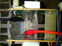
*Just to make sure I've got the Alligator-Clips on the Emitter's Correctly, I have posted a Pic of the Clips on what I have calculated to be the Emitters.
So - Is this Right?!? And if measuring in millivolts (mV), does the following Math sound Accurate? : 20mA x 2(.33Ω) = 13.2mV, 0.020A x 0.66Ω = 0.0132v = 13.2mV
Or should the millivoltage be different? Given the Service Manual says to measure in mA, and wants 50mA per Channel (25mA per Par of Transistors).
Just making sure I've got this all Right before I go to adjust the Bias Current.
Craig - So, even though the Service Manual says to set VR's 3 & 4 [Bias Current Trims] all the way CLOCKWISE, you say it should be the Opposite?!?
Anyways, I think I've about got this AU-11000 back together.
I will be doing the Bias Current Adjustment FIRST on each channel.
Because I only have 1 Multimeter, I will have to do each channel independently. Which means I'll have to turn-off the Amp after I do one channel, connect the Alligator-Clips to the other channel, and turn the Amp back on to adjust the Bias Current for that channel.
*Just to make sure I've got the Alligator-Clips on the Emitter's Correctly, I have posted a Pic of the Clips on what I have calculated to be the Emitters.
So - Is this Right?!? And if measuring in millivolts (mV), does the following Math sound Accurate? : 20mA x 2(.33Ω) = 13.2mV, 0.020A x 0.66Ω = 0.0132v = 13.2mV
Or should the millivoltage be different? Given the Service Manual says to measure in mA, and wants 50mA per Channel (25mA per Par of Transistors).
Just making sure I've got this all Right before I go to adjust the Bias Current.
Attachments
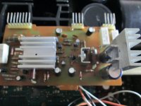
Try these computer heatsinks on your regulator/protection board F-2568. It gets really hot in there with a lot of heat coming from those 5W resistors. You can see in the photo how they clip onto the heatsinks that are already there,Ive taken one off and sat it on the capacitors. I use a bit of thermal grease to slide them into place,its as if they were made for it.
Attachments
Last edited:
- Status
- Not open for further replies.
- Home
- Amplifiers
- Solid State
- Sansui AU-11000 output emitter short.