So you've blown it up 😉 What happened depends on what you you shorted to what.
Are you sure the voltages are all good? If that is so then all the following will be correct
Both supplies correct, the - and +?
Is the offset zero?
Is the bias current correct and adjustable?
If any of the above are incorrect then you must logically begin fault-finding on the issue you know is wrong.
Supplies first, offset next, then bias current.
So you've blown it up 😉 What happened depends on what you you shorted to what.
Are you sure the voltages are all good? If that is so then all the following will be correct
Both supplies correct, the - and +?
Is the offset zero?
Is the bias current correct and adjustable?
If any of the above are incorrect then you must logically begin fault-finding on the issue you know is wrong.
Supplies first, offset next, then bias current.
Thanks Mooly.
Unfortunatelly I've shorted base with collector of the right channel's old 2SB507 (which was working brilliantly) and now I have to check around there.
The thing is that the transistor itself tested good with a normal diode test and all voltages of this channel are according to the manual.
For the other channel all supplies correct.
Where do I measure offset? Collectors TR604-TR605? It's 0V there.
All voltages correct up to TR05 (staring from TR1 and all the power supply and head amp section). The collector there shows -3.4V instead of -1.2V for the left channel. The right channel's same transistor TR06 has -1.2V which is correct.
After that all the voltage around TR07-09-11-13 seem higher than the ones of the right channel.
The bias seems adjustable for the voltage (+- 0.3V). But the voltage is really harmfully high I guess.
Shorting C and B has applied full negative supply to the amplifier output...
I would be surprised if the transistor survived that. The first thing to do is to check all those low value resistors in the output stage. You can test those in circuit. The 0.33 ohm the 6.8 and 220 ohms. Check them all.
DC offset is the voltage appearing at the junction of the 0.33 ohm's. It should be zero.
If TR05 collector is at -3.4 volts then there is a problem but we don't know where until you do all the measurements.
Why not measure and record the voltages for TR05 TR9 TR11 TR13 and TR15.
Copy and paste this and fill in all the readings.
TR05
E=
B=
C=
TR09
E=
B=
C=
TR11
E=
B=
C
TR13
E=
B=
C=
TR15
E=
B=
C=
This should show where any problems are.
Thanks again.
Dc offset around 10-20mV.
one 6.8 resistor open on the left channel. Replaced with another that measures 6.1.
All other resistors good values. Impossible to measure the 0.3 ones with my DMM. It seems like they are correct since it shows around 0-0.2
Coming back with the voltages
Dc offset around 10-20mV.
one 6.8 resistor open on the left channel. Replaced with another that measures 6.1.
All other resistors good values. Impossible to measure the 0.3 ones with my DMM. It seems like they are correct since it shows around 0-0.2
Coming back with the voltages
Shorting C and B has applied full negative supply to the amplifier output...
I would be surprised if the transistor survived that. The first thing to do is to check all those low value resistors in the output stage. You can test those in circuit. The 0.33 ohm the 6.8 and 220 ohms. Check them all.
DC offset is the voltage appearing at the junction of the 0.33 ohm's. It should be zero.
If TR05 collector is at -3.4 volts then there is a problem but we don't know where until you do all the measurements.
Why not measure and record the voltages for TR05 TR9 TR11 TR13 and TR15.
Copy and paste this and fill in all the readings.
TR05
E=
B=
C=
TR09
E=
B=
C=
TR11
E=
B=
C
TR13
E=
B=
C=
TR15
E=
B=
C=
This should show where any problems are.
Here we are.
I also measured the right channel similar transistors which doesn't work anymore (it gives a very very weak distorted sound on both speaker and headphones).
The left one gives a weak distorted sound on the speaker (like one of its sides has died) but a good sound on the headphones.
TR05
E= -25,7v
B= -25V
C= UNSTABLE -2.3 - -2.5V
TR07
E= -2.9V - -3.2V
B= -2.5V
C= -1V
TR09
E= 2mV
B= -1.1V
C= 26.5V
TR11 (BC327 replacement - POSSIBLE CAUSE)
E= -2.9V
B= -3.2V
C= -26.5V
TR13 (2SD313)
E= 2.5mV
B= UNSTABLE 2 - 70 mV
C=26.6v
TR15 (2SB507)
E= 2.5mV
B= 2.5mV
C= -26.5V
TR06
E= -25,7V
B= -25V
C= -1.2
TR08
E= -1.1V
B= -0.5V
C= 1.2
TR10
E= 0.6V
B= 1.2V
C= 26.5V
TR12
E= -0.6V
B= -1.2V
C= -26.5V
TR14 (TIP41C)
E= 2.5mV
B= 0.6V
C= 26.5V
TR16 (TIP 42C)
E= 2mV
B= -0.6V
C= -26.5V
TR05 collector and TR11 base should be the same point, and so the same values.
Apart from that though nothing very obvious stands out... no shorts or open circuit.
Lets concentrate on the RIGHT channel only. This is a real puzzle because the voltages here are pretty much spot on where they should be.
You have no offset and the output transistors are on the verge of conduction. The voltages on the drivers are correct as well.
Remember you have the amp in front of you, I don't. so some of this may sound a bit odd but its the only to know what is going on.
1/ Have you tried a different speaker on this channel? Reason for that is if any previous DC fault has damaged the one you are using.
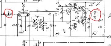
2/ Have you an oscilloscope? Can we be certain the audio at the input to the power amp is clean (so C01 it looks like on the diagram).
3/ Are the mute transistor OFF? That is TR604 and 605. There should be the negative voltage on the base as shown on the diagram.
Apart from that though nothing very obvious stands out... no shorts or open circuit.
Lets concentrate on the RIGHT channel only. This is a real puzzle because the voltages here are pretty much spot on where they should be.
You have no offset and the output transistors are on the verge of conduction. The voltages on the drivers are correct as well.
Remember you have the amp in front of you, I don't. so some of this may sound a bit odd but its the only to know what is going on.
1/ Have you tried a different speaker on this channel? Reason for that is if any previous DC fault has damaged the one you are using.
2/ Have you an oscilloscope? Can we be certain the audio at the input to the power amp is clean (so C01 it looks like on the diagram).
3/ Are the mute transistor OFF? That is TR604 and 605. There should be the negative voltage on the base as shown on the diagram.
TR05 collector and TR11 base should be the same point, and so the same values.
Apart from that though nothing very obvious stands out... no shorts or open circuit.
Lets concentrate on the RIGHT channel only. This is a real puzzle because the voltages here are pretty much spot on where they should be.
You have no offset and the output transistors are on the verge of conduction. The voltages on the drivers are correct as well.
Remember you have the amp in front of you, I don't. so some of this may sound a bit odd but its the only to know what is going on.
1/ Have you tried a different speaker on this channel? Reason for that is if any previous DC fault has damaged the one you are using.
2/ Have you an oscilloscope? Can we be certain the audio at the input to the power amp is clean (so C01 it looks like on the diagram).
3/ Are the mute transistor OFF? That is TR604 and 605. There should be the negative voltage on the base as shown on the diagram.
Thanks for your precious time Mooly. You really help me with this difficult quiz.
1/ Both speakers work really well with any other system. As I've mention before. The left channel speaker sounds brilliant for some seconds when I switch off the amp. The right channel doesn't give any serious signal on the headphones too.
2/Yes I have one and yes the audio is clean up to the output and reacts well to the volume pot. Around CO2 (that's the one for the right channel it's half to the one on the input and poit of entrance 02) , but then it goes back to normal on the out.
The problem is the quality of the sound. The signal generator is just plain frequencies. And it shows no obvious distortion. I've tried sine wave frequencies of 1-2 V from 40 hz to 20kHz. All good. With music it's a different story.
3/I have no idea how to switch them. The voltages seem good to me. Base -0.3V, B and C 0 and -0.1mV in both of them
tr15.......e-b ?
short?
Maybe. But this is the left channel which has problems in all the transistors from TR05 to TR15. It's a chain around the bias pot.
For the time being we 're focusing around the right channel which is dead even on the headphones, even if the voltages are much better around the transistors.
I also tested all resistors after the output transistors. All good. The ones on the coils need to be taken off board, because the coil prevents them from showing any resistance.
Is there any possibility to have problems with the coils- inductors? Can they be damaged or fail?
Is there any possibility to have problems with the coils- inductors? Can they be damaged or fail?
Very unlikely for any coils to be faulty, and also any of the components after the output transistors.
The mute transistors will be OK if they have -0.3V on the base.
Have you got the speaker attached when looking at the sine wave test tones?
The signal should be clean on the cap shown here. If you set the signal level to 100mv peak to peak on the cap, how much signal do you see on the output and does it look distorted or not.
Attachments
It is very unusual to have an amplifier where the DC conditions are correct and yet the sound is poor/distorted/low etc.
I think one test you should do is to see if the DC bias current adjusts correctly. Connect your meter across the tests points (so between the emitters of the two output transistors) and without any load attached or signal applied see if the pre-set works correctly.
100 milliamps (as a quick test value to make sure it adjusts normally) would be a voltage of 66 millivolts across the combined resistance of the 0.33 ohms (V= 0.1/0.66).
If that does work OK then set the value back to 13 millivolts between the test points.
Very unlikely for any coils to be faulty, and also any of the components after the output transistors.
The mute transistors will be OK if they have -0.3V on the base.
Have you got the speaker attached when looking at the sine wave test tones?
The signal should be clean on the cap shown here. If you set the signal level to 100mv peak to peak on the cap, how much signal do you see on the output and does it look distorted or not.
That was a good one.
Things changed when I plugged headphones on the out.
I don't want to add good speakers during test with signal generators for obvious reasons (frequency and voltage drop outs etc.). I haven't got cheap passive ones around.
So what I see on the out is totally different for the right channel. It just shows two separate lines moving. The signal comes out of the headphone can reacting properly to the volume pot.
On C06 negative side (where you show me) the signal is about 5mV. Not a bad-distorted shape but 20 times reduced in volume. I used a 100mV sine wave of around 3khz.
For the left channel the waveform changed on the out as well...quite unstable and distorted. But we'll get back to it (for the left channel) later.
It is very unusual to have an amplifier where the DC conditions are correct and yet the sound is poor/distorted/low etc.
I think one test you should do is to see if the DC bias current adjusts correctly. Connect your meter across the tests points (so between the emitters of the two output transistors) and without any load attached or signal applied see if the pre-set works correctly.
100 milliamps (as a quick test value to make sure it adjusts normally) would be a voltage of 66 millivolts across the combined resistance of the 0.33 ohms (V= 0.1/0.66).
If that does work OK then set the value back to 13 millivolts between the test points.
Sorry I'm losing you Mooly.
Do I switch to current on my DMM and place the red probe on the emmiter of Transistor 14 and the black on the emmiter of transistor 16 on TP02 - TP04? And then I set the bias pot to 100mA? (This is how I was checking the bias so far - I was just playing around 20mA)
And then I switch to voltage and I place the black on ground and red on each test point looking for 13mV on each one? Is this right?
Hi tedsorvino1,
You know, there never was a fault in the amplifier section. You have a dirty contact in the headphone jack.
If your DC conditions are okay, leave that poor amplifier section alone and clean the headphone switches as they also cut the speakers out. You may have to clean the switches from the rear of the jack, then work the headphone plug in and out.
You missed the one clue that told you everything. Headphone output okay, speaker low level and distorted. That was followed by a bunch of assumptions that were incorrect.
-Chris
You may be right about my incorrect asumptions anatech and I guess you know many more things than me, but your assumption is incorrect this time too.
I had cleaned all ins and outs first thing some days ago before I even switch on the amp for the first time - and trust me it's not the first time I clean an output.
Thanks anyways for the input. Of course I may have a faulty output since it's a switched one.
If you have any other idea regarding the problem(s) you 're most welcome and it would really help. Cheers.
Last edited:
Sorry I'm losing you Mooly.
Do I switch to current on my DMM and place the red probe on the emmiter of Transistor 14 and the black on the emmiter of transistor 16 on TP02 - TP04? And then I set the bias pot to 100mA? (This is how I was checking the bias so far - I was just playing around 20mA)
And then I switch to voltage and I place the black on ground and red on each test point looking for 13mV on each one? Is this right?
It is voltage we are measuring between the test points, not current. The current is determined by calculation.
We have to do it that way because your meter is like a short circuit when on the current range and so it would effectively short the 0.33 ohm resistors out and the readings would be different as soon as you removed the meter.
I wanted you to see if the bias would increase correctly as you alter the setting... yes 100ma is far to high to leave it like that but we need to know it works as it should.
So connect your meter on DC volts and check the voltage between the test points can be increased to around 66 millivolts. Then reset it back to 13 millivolts.
Great insight Mooly. Much appreciated. Actually without the theoritical background I 've learnt about current the hard way during previous tube bias work.
Back to our task.
This is what I was doing so far.
And yes the right channel can give more than 90millivolts - it's actually very reactive after a certain point.
The left channel one doesn't give any measurement.
The right channel gives no good sound whatsoever.
The left gives good sound on the headphones and when it shuts down.
Last edited:
Lets stick with the right channel.
So the bias does indeed adjust correctly... this is really bizarre you know🙂
First thing is to set the bias back to the correct level which is around 13 millivolts between the test points.
We have to look at this dynamically now. Make sure things like the tone controls are centred (because these are part of the feedback loop for the power amplifier) and set the scope and signal generator up again.
Have NO speakers or headphones connected.
Apply a known amplitude sine to the input, lets say we use 100mv peak to peak again and 1Khz. Measure this on the input coupling cap I circled earlier. Be certain you have 100 millivolts peak to peak.
Now tell me what the peak to peak amplitude is at the output. Measure on that coil at the output.
What peak to peak amplitude do you see?
Is the sine clean or is it distorted looking?
Now plug the headphone in.
Has the amplitude or shape changed?
My best guess is that the amp runs at pretty high gain (it's not easy to determine because of the tone controls acting within the feedback loop and the use of log pots) however I think you will see around 8 volts peak to peak for 100 millivolts peak to peak input.
- Home
- Amplifiers
- Solid State
- Sansui amp keeps blowing fuses after output transistor replacement.