Hi All,
I'm having trouble with the muting circuit. On initial startup (before protection relay clicks) muting works as designed...TR602,603 & 604 all operate as they should. Once the protection relay clicks and the receiver is operational, TR602 closes, mute disables and all is fine. As the system continues to operate TR602 slowly starts to turn back “on“ until eventually (within 10 minutes) the muting circuit is fully activated and signal to the amp section is greatly reduced. I've cleaned the phono push button and selector switch thoroughly, replaced TR602 to KSA992 and TR603/604 to KSC1815. The diodes test good in-circuit. Now I'm just doing stupid stuff like testing resistors where the likelihood of them being defective is near zero. Somehow it seems there's leakage preventing TR602 base voltage from raising high enough to keep this transistor closed during regular operation. I was thinking it was an heat issue, however, with DMM monitoring TR602 collector, the transistor starts the slow process of turning itself on right away, with voltage steadily climbing until muting activates. Any thoughts would sure be appreciated?
Thanks,
D
Attachments
Welcome to the forum!
Thanks for adding missing values to the first schematic—- made it much easier to sort out the circuit.
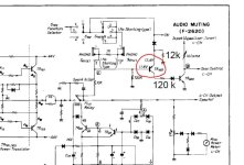
As I interpret the first schematic, there should be an intact path from +13VDC through S702d, to S01c, to 1k resistor, to S01d, to node C—- ie base of Q602. This resistor should show 1k continuity from +13 to base Q602 and should hold the transistor in cutoff. I suspect an open somewhere in this path. With an open and rising temperature, leakage in Q602 rises enough to assert muting.
Good luck!
Thanks for adding missing values to the first schematic—- made it much easier to sort out the circuit.
As I interpret the first schematic, there should be an intact path from +13VDC through S702d, to S01c, to 1k resistor, to S01d, to node C—- ie base of Q602. This resistor should show 1k continuity from +13 to base Q602 and should hold the transistor in cutoff. I suspect an open somewhere in this path. With an open and rising temperature, leakage in Q602 rises enough to assert muting.
Good luck!
Last edited:
Thanks so much for your comments. I went deeper into the switch circuit and found that the expected 1k resistance was sitting at 0.840k…so there are some losses in there. Out of circuit a solid 1k. I believe Sansui probably ran that muting circuit quite close to the turn on voltage for TR602. So I ran another 1k resistor in parallel with the existing one and this has balanced the 602 base and emitter voltages perfectly. Muting circuit is no longer as sensitive as it was previously but she’s back in service. Interestingly on this unit there were 8 transistors and 1 IC (had to install discrete component replacements) on the tone and eq board that had failed. Never seen anything like that…perhaps this unit spent a few too many hours with an LP cover blocking the vent. Thanks again BSST.
