Looks golden on the center, left ,and right amps, but the rear is different and doesn't look very upgradable so you might be stuck at 50 watts for that one. However, check the data sheets on those transistors, I'm guessing you can or can make it so it's ok on the same voltage as the other three amps. Oh and make sure that fan can still run! Good luck!
Sorry, I think my pictured were not good enough. Below is the picture of the strip-down chassis, leaving only power amplifier board along with output speaker relays, power supply and a regulator board(for the op-amps and relays).
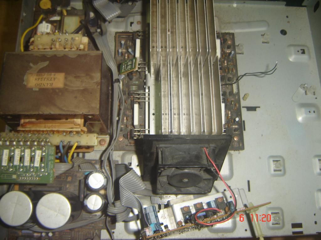
So As you see, it has 4 channels, Front Left, Front Right, CENTER and REAR. I checked, all parts are identical, but rear runs on a lower supply voltage(separate secondary tapping, rectifier and filter caps). FRONT L, R and Center runs on the main rails.
Those 4 dual 0.33Ohm(white color) resistors marks each of the separate channel. I just completed my Denon PMA-680R Recap... Next is a Pioneer A400. Then I will take up this baby...
Last edited:
I have uploaded a picture shown all 4 sides. But All sides have same components and same PCB routing...Hi, I can only see a board for front L and front R. rgds, sreten.
On J21, the DC protection and overload protection go off-board, so you'll have to deal with those and adding relays on the 4 outputs. I would keep the headphone connections on J26. And on c17 and 18 be sure to connect the grounds when running to rca's. Add a 4.7uF 50V cap (I like Nichicon FG personally) in front of the L and R channels for DC protection.
Hi,
Thanks, I will be using 4.7UF Panasonic Polypropylene capacitors for signal line coupling, I have to go back and see the circuit to see, which all relays I need to hardwire. One thing will be the secondary (standby) transformer... Which is micro-controller controlled to switch on the main Amp section. Now I have to to try and see by powering the main amps directly.
I will re-capp all the electrolytic capacitors, I normally use Panasonic FC or Nichicon KZ. I will also will change most of the ceramnic caps. That's all I have in mind now as "upgrade".
One thing will be the secondary (standby) transformer... Which is micro-controller controlled to switch on the main Amp section. Now I have to to try and see by powering the main amps directly.
I am confused on why you can't just use a physical switch.
Hi,
Great amplifier for active / passive biamping IMO,
if passive reduce the input cap on the rear/centre
to get rid off bass, the lower voltage won't matter.
Change the centre to run on the rear supply.
rgds, sreten.
Great amplifier for active / passive biamping IMO,
if passive reduce the input cap on the rear/centre
to get rid off bass, the lower voltage won't matter.
Change the centre to run on the rear supply.
rgds, sreten.
Last edited:
I am confused on why you can't just use a physical switch.
No No No. Don't get me wrong. I will be indeed hardwiring the power switch and removing the standby.. Most probably!
No plans to keep AVRs Micro-controller anyway 🙂
Hi,
Great amplifier for active / passive biamping IMO,
if passive reduce the input cap on the rear/centre
to get rid off bass, the lower voltage won't matter.
Change the centre to run on the rear supply.
rgds, sreten.
Not sure whether possible to run Center from Low Voltage, because that may involve cutting multiple tracks. But I surely can run rear from High voltage rail... By giving the same rail lines on the JST connectors for power (or whatever that connector is called). And then may be do an active Bi-Amp, with high pass filters for center and rear which will reduce power consumption of those channels making the main supply lines, enough to power all the speakers.
Oh, while I am at it, should I change all the 5% carbon film resistors with 1% MFRs? May be on this kind of design, it may not really matter huh?
Last edited:
Oh, while I am at it, should I change all the 5% carbon film resistors with 1% MFRs? May be on this kind of design, it may not really matter huh?
I wouldn't. tedious and won't offer any significant gain like you said.
I wouldn't. tedious and won't offer any significant gain like you said.
And how about those Ceramics, better to leave them alone too? Or selectively replace looking at the circuit(leaving RF blocking and Electrolytic Cap bypass caps unchanged and changing rest from ceramic to Polypropylene/Polyester/Polystyrene)?
And how about those Ceramics, better to leave them alone too? Or selectively replace looking at the circuit(leaving RF blocking and Electrolytic Cap bypass caps unchanged and changing rest from ceramic to Polypropylene/Polyester/Polystyrene)?
As long as the ceramics are NPO, I would leave them be. They have characteristics that make them good to be used in these situations.
If you don't know what the capacitor does, don't replace it with another type. Also, I think the circuit designer knew what s/he was doing. Upgrading their design in such a simple way is unlikely to be a possibility.And how about those Ceramics, better to leave them alone too? Or selectively replace looking at the circuit(leaving RF blocking and Electrolytic Cap bypass caps unchanged and changing rest from ceramic to Polypropylene/Polyester/Polystyrene)?
- Status
- Not open for further replies.
- Home
- Amplifiers
- Solid State
- Salvaging the Power Amp sections of 90s Prologic