Hi,
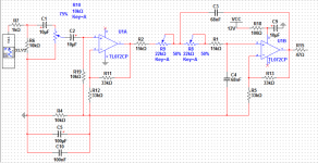
I've designed an amplifier based on the TDA1516BQ, 4X highpass and one lowpass. filter topology is a sallen-key with 2X gain.
The problem arises with the lowpass filter. On pin 7 of the TL072 (the inverse input of the second opamp), the only thing i get is a loud hum. But at the output the filter seems to be in working order. I tested this with an audio probe, only the volume is very low (almost the same as the non-inverting input from the second opamp, it doesn't seem to amplify).
I already tried different powersupply's to no effect. Even with a 9V battery the hum was present. So by this i can rule out a problem with the supply.
The thing i did wat seem to work, was removing the cap to ground at the second amps Rf and Rg resistors (gain setting). The hum was gone and the filter worked but no amplification.
The high pass filters work perfectly without distortion
I hope somebody can help me its driving me nuts...
Attachments
I'm not sure that the TL072 can be operated from a single supply...
It doesn't look like the Vcc/2 reference to which the audio "grounds" should be connected is properly implemented in your circuit. Another resistor in the same place as R19 should connect to Vcc instead of C2. The value of this new resistor and R4 should be much less than the values for the feedback network resistors that connect to it (e.g. R19, R11, R12, R5, R13), which need to source/sink current to the reference. You do not want that current to disturb the reference voltage. Changing the two resistors that establish the Vcc/2 reference from 10k to 1k or less would be a better choice.
It doesn't look like the Vcc/2 reference to which the audio "grounds" should be connected is properly implemented in your circuit. Another resistor in the same place as R19 should connect to Vcc instead of C2. The value of this new resistor and R4 should be much less than the values for the feedback network resistors that connect to it (e.g. R19, R11, R12, R5, R13), which need to source/sink current to the reference. You do not want that current to disturb the reference voltage. Changing the two resistors that establish the Vcc/2 reference from 10k to 1k or less would be a better choice.
Last edited:
The opamps can be operated from a single polarity supply, but the whole circuit has to be converted to AC coupled to ensure the opamps and their signals all stay within the operating limitations of the supply.
The circuit as posted is designed for a dual polarity supply.
The circuit as posted is designed for a dual polarity supply.
33k resistor on the -IN pin will be noisy.
Try reducing to 2k, the tl072 should be able to drive 2k in parallel to the load. See datasheet.
U1A is a Buffer. Omit R12 and change R11 to 1k, or 0r0.
The ratio of R13:R5 is wrong.
Check your source for proper values.
Try reducing to 2k, the tl072 should be able to drive 2k in parallel to the load. See datasheet.
U1A is a Buffer. Omit R12 and change R11 to 1k, or 0r0.
The ratio of R13:R5 is wrong.
Check your source for proper values.
Last edited:
Hi,
I changed the schematic, accordingly. But the problem still persists, the output from the first amp has gain without distortion. You can hear the difference clearly. But the second amp with the sallen key and 2X gain integrated, gives me a very loud hum on the inverse of the op amp even with a 9 volt battery connected. This configuration worked before but suddenly this damn humming appeared on the amp 🙁
Another thing I triend was switching the amps. The sallen key first but with unity gain. and the second amp for increasing the signal with a gain of 1.
I tried to increase the gain of the second amp but the output volume is very low and distorted. (Almost sounds like clipping in low volume?)
The amp can swing between +6 en -6 volt if connected to a 12 volt source. As i sad before i've build 4 high pass filters with 2X gain. The configuration is almost the same as the schematic below, but with RC swapped.
I tried changing the 33K for a 2 K. Problem still persist.
I'm running out of options. Any help would be appriciated
Attachments
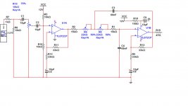
you are still showing the single polarity supply to the opamps, even though the circuit is designed for dual polarity supply.
I dont understand what you mean. The first opamp has a DC bias of 6v this gives me 6V on the noninverting input of the second opamp as a DC bias, that's the reason why R12 and R5 are connected by a cap to ground.
The circuit looks OK as far as DC conditions go. Both opamp outputs should be at approx. half supply voltage.
Opamps and amplifiers don't hum. If there is a hum noise present then it is because of a problem connecting it all up.
If you remove C3 and C4 then the circuit should pass audio. The 33k's give each stage a gain of two. You will soon run into clipping with a line level input and a 9 or 12 volt supply.
The way the schematic is drawn, if two wires touching are connected there's a blob. But your second opamp doesn't have a blob to make the connection between pin7 and the feedback resistor. Could this be a clue to your problem? Added to that in your original post you said pin7 was the inverting input - its not, its the output.
Yes, i tried that to it will pass audio but then off course without filtering. I noticed that during PSU switch off for a short moment everything worked normally gain restored etc.
I came to the same conclusion about the PSU's max supply thats why I changed the schematics by only giving the second amp gain and the first with the active filter unity gain. But the problem still persist
I came to the same conclusion about the PSU's max supply thats why I changed the schematics by only giving the second amp gain and the first with the active filter unity gain. But the problem still persist
Attachments
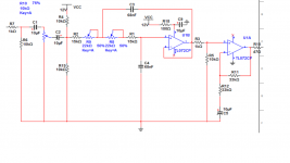
Why not try running your circuit off a couple of series 9 volt batteries to see if it works. The current consumption is very low and so it should all work perfectly.
The TL072 latch up problem when common mode range is exceeded. Can this be the culprit during startup in this single supply circuit?
Hi
I suspect your circuit is oscillating. Go back to the schematic in post #5 and set R18 =0. It is too big. If you need it because of noise on the power, then set it to 10ohm and set C9 = 100u.
Lars
I suspect your circuit is oscillating. Go back to the schematic in post #5 and set R18 =0. It is too big. If you need it because of noise on the power, then set it to 10ohm and set C9 = 100u.
Lars
Sallen and Key turns into an oscillator if the gain is greater than 2. S&K works by positive feedback, and the q goes way up at gain of 2. (In fact, a simple way to adjust the Q is to adjust the gain. So either adjust the gain for the Q that you want (with equal RC it is .5 at gain of 1) or go to gain of 1 and adjust the Cap values for the Q you want.
Looked at your post 10 - S&K circuit is Q of .5 but your source resistance (from DC offset circuit and input level control) is going to affect the first resistance in the S&K circuit. Another issue may be that your gain circuit may latch up when turning on, until the C5 cap gets charged up. With single supply, I'd try two 68K ohms between the supply and ground with no cap (or maybe a 100 ohm resistor and bypass cap like on the supply to the op amp.) good luck.
- Status
- Not open for further replies.
- Home
- Amplifiers
- Chip Amps
- sallen-key low pass issue