I've searched the forum, but I found no info on this (granted I didn't spend hours searching).
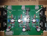
I have this (PCB designed by dvb-project) fully populated, except for the current limiting resistors. I left those unpopulated as I don't know what values to use. The LED's are matched and the 2SK170BL's are all matched within 0.01mA(not that it's needed, but I had 16pcs matched within +/-0.01mA).
So, if anyone knows what values to use for the 5W current setting resistors, I'd be grateful if they'd share that information.
Attachments
No idea, but dvb-projekt ist here on diyaudio. Send him a PM.
Yes I know he's on the forum, for some reason I didn't think to message him though.
Thanks 🙂
I've searched the forum, but I found no info on this (granted I didn't spend hours searching).
I have this (PCB designed by dvb-project) fully populated, except for the current limiting resistors. I left those unpopulated as I don't know what values to use. The LED's are matched and the 2SK170BL's are all matched within 0.01mA(not that it's needed, but I had 16pcs matched within +/-0.01mA).
So, if anyone knows what values to use for the 5W current setting resistors, I'd be grateful if they'd share that information.
Hi Mayday,
attached you find the BOM from the whole project. Also the value 10R/5W of the Current setting R´s. 😉
Best regards,
Oliver
Attachments
Last edited:
Hi Mayday,
attached you find the BOM from the whole project. Also the value 10R/5W of the Current setting R´s. 😉
Best regards,
Oliver
Hi Oliver,
Thank you 🙂
I have three of the V5 Red Baron boards.
I'm thinking of using two in parallel or simultaneous mode, and the third as is so to speak.
It'll be interesting to compare.
All the best,
Jonas
Hi Oliver,Hi Mayday,
attached you find the BOM from the whole project. Also the value 10R/5W of the Current setting R´s. 😉
Best regards,
Oliver
Is 10R/5W enough for each rail with at least 100mA headroom?
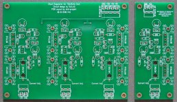
It's the PCB on the left.
Attachments
Yes, go ahead!
Best
Oliver
Hi Oliver,
Thanks for the clarification!
You don't happened to have the schematic for the board on the left?
I've done some quick reverse engineering and the sims comes out with the correct Vout, but with some really weird dissipation for the negative rails.
It may be that my quick reverse engineering was faulty for the negative rails.
All the best,
Jonas
- Home
- Amplifiers
- Power Supplies
- Salas shunt reg for TDA1541A question