have not received pcb
Please Update the list yourselves when you type here:
1 - TFAN69 - 1set
2 - Komigenie - 2 set
3 - pop music - 1 set
4 - Atilla - 2 set
5 - Royalbee - 2 set
6 - h-wan - 3 set
7 - rothay - 3 set
8 - ben-jam-in-3 set
9 - Superluca71 - 2 set
10 - suburra - 2 set
11 - Ed LaFontaine - 2 set
12- Joshua_G – 2 set
13 - dbratny - 4 sets
And ,
Please Update the list not get last PCB:
1. stephen1212
2. fitzfish (received 1 set, still need remaining 3 sets)
3. ramallo
4. claudio
5. kp93300 ( 2sets)
I support Stephen1212's comments.
Bulk tracked delivery to a point in N.America for further distribution.
USPS Delivery Confirmation costs only ~$0.90 and is available for first class post.
I want the low voltage option included.
Bulk tracked delivery to a point in N.America for further distribution.
USPS Delivery Confirmation costs only ~$0.90 and is available for first class post.
I want the low voltage option included.
well stephen, you have to either have gold immersion, or soldermask, otherwise the copper will oxidize, you could go with silver immersion which is cheaper and the sulphide isnt as bad. I also lament the loss of the low voltage regulator and without it or the sense connections (actual connections) I might leave it. you could use less space and provide an easy way to shield the sense wiring by using 2 small SMD coax connectors.
wow I had no idea so many went missing, I fdeel that more than is needed should be ordered (perhaps 10%) and paid for by the group, this 10% will be held over till all boards have been received. I think this will be cheaper than adding tracking to all the deliveries, because this does not solve the issue, you just get to see where it goes missing, good luck getting them to pay you for replacements.
so I will hang back for a bit, but am interested in getting more boards given the low voltage reg is reinstated
I am using this reg for my turntable, a Technics 1200 and it works like a charm. I set it to 21V and I am able to disable the on board transformer and reg. I do get voltage sag during start stop which draws more current than the reg can supply momentarily as I didn;t want to run it too hot. I might set it to more current in the future, but it seems to operate just fine. I seem to get better defined and detailed bass with this reg!
Thanks Salas and Quanghao!! 🙂
Thanks Salas and Quanghao!! 🙂

The constant current start up might be better for the motor.using this reg for my turntable, ...................I do get voltage sag during start stop which draws more current than the reg can supply momentarily.............
If it starts reliably using the existing CCS value, I would be tempted to leave as is.
You could even try reducing the CCS current to find when the Motor protests by not starting reliably and then increasing CCS a few steps.
Last edited:
Please Update the list yourselves when you type here:
1 - TFAN69 - 1set
2 - Komigenie - 2 set
3 - pop music - 1 set
4 - Atilla - 2 set
5 - Royalbee - 2 set
6 - h-wan - 3 set
7 - rothay - 3 set
8 - ben-jam-in-3 set
9 - Superluca71 - 2 set
10 - suburra - 2 set
11 - Ed LaFontaine - 2 set
12- Joshua_G – 2 set
13 - dbratny - 4 sets
14 - rpeter - 3 sets
And ,
Please Update the list not get last PCB:
1. stephen1212
2. fitzfish (received 1 set, still need remaining 3 sets)
3. ramallo
4. claudio
5. kp93300 ( 2sets)
quanghao,
I am confused. I think there are others who with me are confused.
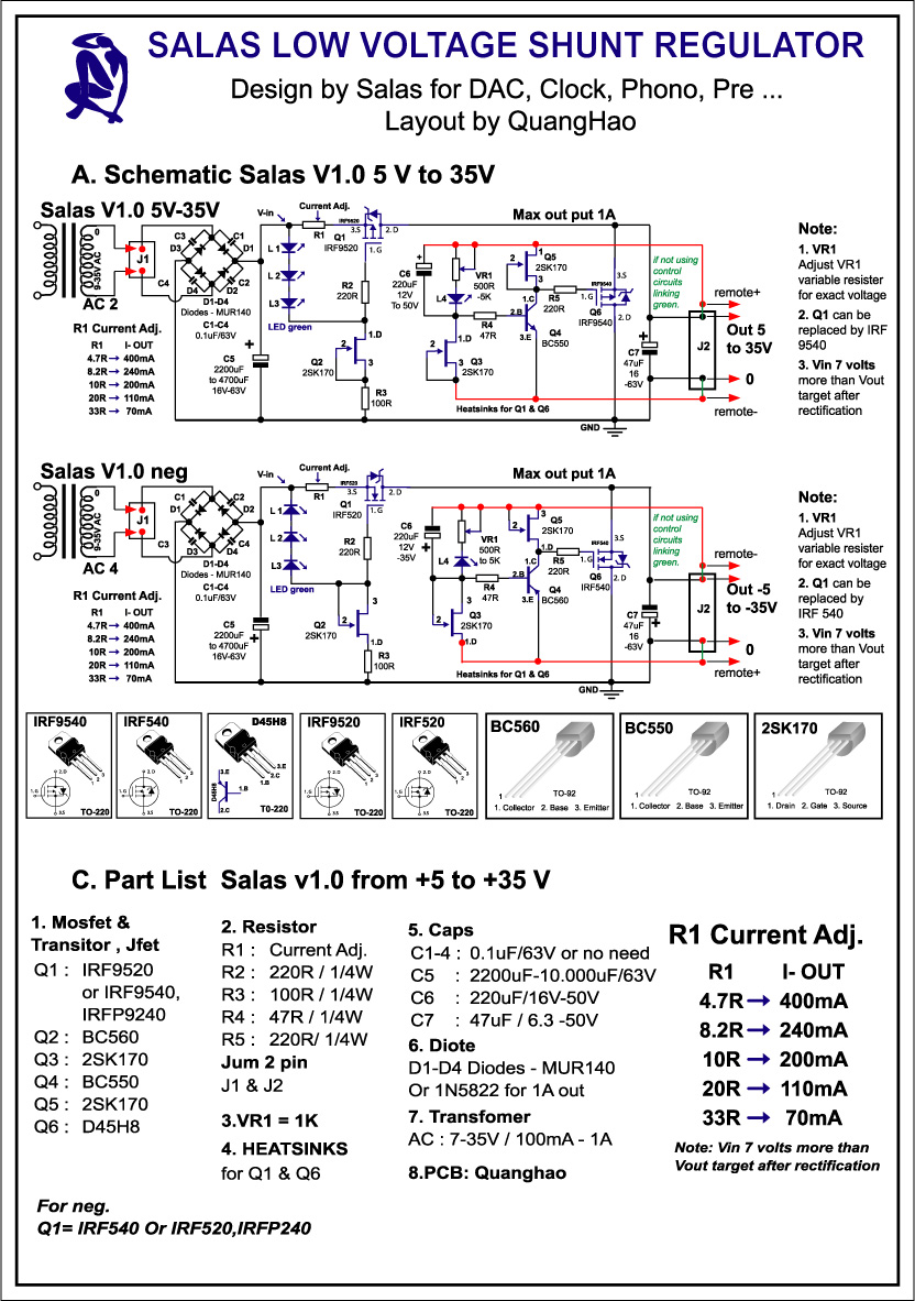
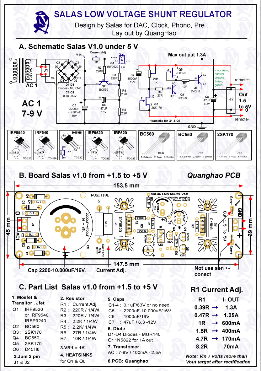
You have included the description for the low voltage board in your post above.
From this are we to conclude that the low voltage board will be included on the set?
Will the sets include 3 or 4 boards?
I am confused. I think there are others who with me are confused.
You have included the description for the low voltage board in your post above.
From this are we to conclude that the low voltage board will be included on the set?
Will the sets include 3 or 4 boards?
quanghao,
I am confused. I think there are others who with me are confused.
You have included the description for the low voltage board in your post above.
From this are we to conclude that the low voltage board will be included on the set?
Will the sets include 3 or 4 boards?
I think 4 or 5PCB on board!
1 -v
2 or 3x + 5V
1 x 1.5 to +5V
it is good??
quanghao,
It is all good. ...and we appreciate all that you are offering.
However, some of your comments are confusing, for example:
I think it will be 4...or 5...and include the 1.5 to +5V board.
I will be happy with that.
It is all good. ...and we appreciate all that you are offering.
However, some of your comments are confusing, for example:
1 + 2 + 1 = 4, that is good...if 5 even better...the confusing part is the "4 or 5PCB on board!"I think 4 or 5PCB on board!
1 -v
2 or 3x + 5V
1 x 1.5 to +5V
it is good??
I think it will be 4...or 5...and include the 1.5 to +5V board.
I will be happy with that.
Last edited:
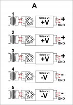
if 5 regs on a PCB, please make the extra one either another negative -5v -> -35v, or low voltage 1.5-5vout regulator. preferably the low voltage
so either
1 -v
2 or 3x + 5V
2 x 1.5 to +5V
or
2 x -v
2 or 3x + 5V
1 x 1.5 to +5V
that would be most excellent!
so either
1 -v
2 or 3x + 5V
2 x 1.5 to +5V
or
2 x -v
2 or 3x + 5V
1 x 1.5 to +5V
that would be most excellent!
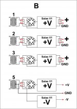
each PCB has it's own rectifier and smoothing.
You don't need +ve & -ve versions.
Make them all -ve version and Nchannel mosFETs can be used throughout.
If one needs a dual polarity supply then all that is needed is a dual secondary transformer and two -ve Shunt regs.
You don't need +ve & -ve versions.
Make them all -ve version and Nchannel mosFETs can be used throughout.
If one needs a dual polarity supply then all that is needed is a dual secondary transformer and two -ve Shunt regs.
Thank you Quanghao
I know you previously indicated a small cap in the output, parallel to the 47u output cap.
Did you have good results with that layout ?
Salas alerted to the possibility of oscilation and you removed the output cap bypass..... Did you ever experiment paralelling a zobel (film + 0,5r) on the output ?
I know you previously indicated a small cap in the output, parallel to the 47u output cap.
Did you have good results with that layout ?
Salas alerted to the possibility of oscilation and you removed the output cap bypass..... Did you ever experiment paralelling a zobel (film + 0,5r) on the output ?
each PCB has it's own rectifier and smoothing.
You don't need +ve & -ve versions.
Make them all -ve version and Nchannel mosFETs can be used throughout.
If one needs a dual polarity supply then all that is needed is a dual secondary transformer and two -ve Shunt regs.
Hi Andrew
I like your approach but I do not understand why you chose two negative shunts.... Why not use two positive shunts and a dual secondary TX ?
..............Make them all -ve version and Nchannel mosFETs can be used throughout.
using -ve shunts avoids the need to buy borrow or steal Pchannel mosFETS.why you chose two negative shunts....
This saves money, makes for easier sourcing and slightly improves regulator performance.
The only down side I can see is that a centre tapped transformer cannot be used.
each PCB has it's own rectifier and smoothing.
You don't need +ve & -ve versions.
Make them all -ve version and Nchannel mosFETs can be used throughout.
If one needs a dual polarity supply then all that is needed is a dual secondary transformer and two -ve Shunt regs.
Hi AndrewT!
you are referring to cases A or B in the figure below, please specify I understand, thank you!
Attachments
Thank you Quanghao
I know you previously indicated a small cap in the output, parallel to the 47u output cap.
Did you have good results with that layout ?
Salas alerted to the possibility of oscilation and you removed the output cap bypass..... Did you ever experiment paralelling a zobel (film + 0,5r) on the output ?
Yes i try do it!
I use : a zobel (film + 0,5r) on the output ,
But i think you can use it or not use, I can put one option for all PCB
- Status
- Not open for further replies.
- Home
- Group Buys
- Salas low shunt Group-design by Salas