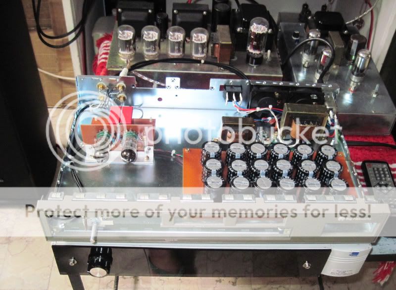
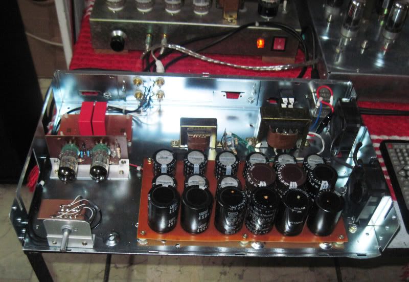
Hi i have got a transformer delivered with
150V and 6.3V secondaries
wanted to use the "salas HV with 3 led Nov09 circuit" , the input is rated as 350V
and output as 300V
can i work with 150V input and output of 135V approx with the trimmer adj.
or some other mods needed ??? The schematic is this one
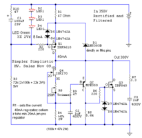
150V and 6.3V secondaries
wanted to use the "salas HV with 3 led Nov09 circuit" , the input is rated as 350V
and output as 300V
can i work with 150V input and output of 135V approx with the trimmer adj.
or some other mods needed ??? The schematic is this one

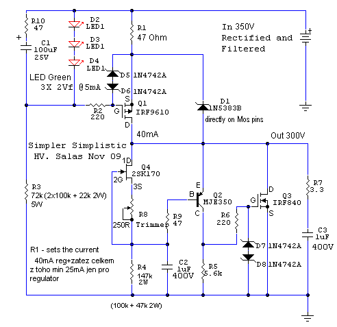
sorry for mini thumnail by mistake the circuit is this one
A) will it regulate 150V ?
B)can i make the filament supply with 4148 bridge rectifier out putting 6.3V?
If you rectify the 6.3V output you will get close to 8.9V at 0.707x the original current rating. You will have to regulate this down to get 6.3 for heaters. Why do you want to use DC on your heaters?
The Salas regulator can regulate 150V, however you will get close to 212V as the input of the regulator if you FWB rectify the 150V output. So you have to watch dissipation. How much current do you need?
You can change the regulation set-point by changing the value of R4.
The Salas regulator can regulate 150V, however you will get close to 212V as the input of the regulator if you FWB rectify the 150V output. So you have to watch dissipation. How much current do you need?
You can change the regulation set-point by changing the value of R4.
The Gimp warns of the problem.
The 150Vac winding when rectified will give ~210Vdc +15% -10% depending on mains voltage and loading.
Assuming +15% on 210 gives ~240Vdc
If you regulate down to 135Vdc then the CCS has to drop 105V. It will get mighty hot !!!!!!!
At the other end if your rectified is low by 10% you have ~190Vdc. This leaves a CCS Vdrop of 55V when in worst case. This CCS will not drop out in worst case loading.
This is the clue that you have a transformer that at 150Vac is far too high for your 135Vdc requirement.
Check out a 120Vac transformer at worst case highest and lowest voltages.
Last edited:
Thank you for the inputs .
@TheGimp i am new to the tubes
so i can guess Ac for filaments is fine .The transformer the sec windings are 6.3 -0 - 6.3 V planning to use 2 filaments of 12AX7 series .
>>> simple resistor dropping is fine ? or a CCS is recommended ? (how bad will it sound with filament unregulated )
@Andrew
There is no requirement to keep 135V i think 175V also is fine with 12AX7
i would use what ever the HV salas gives me as the tubes can also take 300V .
Planning to use in a SRPP configuration .
I have only 330Uf 200V cap for filtering , i hope it will not blast
>>>Please suggest a dummy load (220k resistor ?)to test the HV section , cant risk the tubes
Last edited:
If you are building an SRPP stage, you need more than 150V. 200-300 would be good for SRPP.
You will need to elevate the heater supply.
What are you doing with SRPP stage?
Mr Blencowe (aka Valve Wizard) a good article on the SRPP and optimization of it.
The Valve Wizard- SRPP
see the blue link "The Optomized SRPP amp".
You will need to elevate the heater supply.
What are you doing with SRPP stage?
Mr Blencowe (aka Valve Wizard) a good article on the SRPP and optimization of it.
The Valve Wizard- SRPP
see the blue link "The Optomized SRPP amp".
I am planning to do a simple preamp
I am happy to get a 256V after rectification connected a 56K+redled (very tiny load )
i have not yet given power to the SALAS HV circuit.
worried about the filter cap rated 200V (it may blow i guess)
only way is to go market and put a 100Uf 400V part ,
i have a 2.2uf 400uF capacitor if i remove the 330uF , only 2.2uF will not be sufficient .
@TheGimp that page lists good info on 12Ax7 SRPP thanks
Last edited:
I used AC to my heaters and got pretty much zero noise.
I just used resistor dropper to get the right voltages.
I just used resistor dropper to get the right voltages.
your 200Vdc cap is no good for your 150Vac transformer.
I have shown that you could get well over 200Vdc even in average use conditions and around 240Vdc in worst case conditions.
You need to measure what you actually get from your tansformer and then apply the mains tolerance and loading effect to find the lowest voltage that will be the feed into your Regulator.
Your output should then be set to ~10V below your lowest input voltage.
But do you need a regulator?
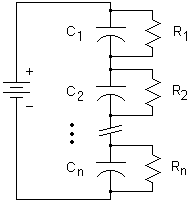
If you have a second 200V capacitor, you can stack them on top of each other with balancing resistors and achieve 400V ability. As such, the capacitance will be divided by two for 165uF vs 330uF.
ya cap change is needed but i liked the idea by TheGimp,i have 2 200volters..please point me how to use balancing resistors
from Capacitors - Multiple Capacitors
For 2 capacitors in series: R = (2Vm - Vb) / (0.0015 C Vb)
For N > 2 capacitors: R = (NVm - Vb) / (0.0015 C Vb)
where R = resistance in megohms
Vm = max voltage you'll permit on either capacitor
Vb = max voltage across the entire bank of two (or N) capacitors
N = number of caps in series
C = capacitance in microfarads
Vb=250V
Vm=215V
N=2
C=330
R=(2*215- 250) /(0.0015*330*250)
gives balancing resistors 1.45M resistor
My assumpion :
looks like too high resistors to do any huge help ..as Vb is near Vm we can neglect balancing resistors
or use 2 Nos of 470K for duty as practical replacement
For 2 capacitors in series: R = (2Vm - Vb) / (0.0015 C Vb)
For N > 2 capacitors: R = (NVm - Vb) / (0.0015 C Vb)
where R = resistance in megohms
Vm = max voltage you'll permit on either capacitor
Vb = max voltage across the entire bank of two (or N) capacitors
N = number of caps in series
C = capacitance in microfarads

Vb=250V
Vm=215V
N=2
C=330
R=(2*215- 250) /(0.0015*330*250)
gives balancing resistors 1.45M resistor
My assumpion :
looks like too high resistors to do any huge help ..as Vb is near Vm we can neglect balancing resistors
or use 2 Nos of 470K for duty as practical replacement
Hi,
that formula looks like it is using leakage current to determine the maximum resistance allowed across the resistors.
The equation should read:
Then 1M5 would be too high.
Your adoption of 470k is OK.
BUT,
for voltage this high I would seriously recommend you reform your capacitors before you subject them to high voltage.
A 2M2 in series with a discharged capacitor will limit the start up charging current (the electrolyte reforming current) to 0.1mA when Charging Voltage = 220Vdc.
You can reform lots of capacitors at the same time by using a resistor for each capacitor.
A Variac could be used with a smaller resistor value if you start with a low charging voltage and step up the voltage when the charge current falls below 10uA. Then leave the caps at maximum specified voltage for 24hrs. disconnect and leave the caps charged up for a further 24houres. Reform again for a further 24hours. The gap or rest period seems to do something with the chemistry and achieves lower leakage than leaving the caps on for a continuous 72hours at full voltage.
BUT be very careful !!!!!!
no pets, no children and no wife allowed while the caps are at high voltage.
that formula looks like it is using leakage current to determine the maximum resistance allowed across the resistors.
The equation should read:
R < (2Vm - Vb) / (0.0015 C Vb)
Then 1M5 would be too high.
Your adoption of 470k is OK.
BUT,
for voltage this high I would seriously recommend you reform your capacitors before you subject them to high voltage.
A 2M2 in series with a discharged capacitor will limit the start up charging current (the electrolyte reforming current) to 0.1mA when Charging Voltage = 220Vdc.
You can reform lots of capacitors at the same time by using a resistor for each capacitor.
A Variac could be used with a smaller resistor value if you start with a low charging voltage and step up the voltage when the charge current falls below 10uA. Then leave the caps at maximum specified voltage for 24hrs. disconnect and leave the caps charged up for a further 24houres. Reform again for a further 24hours. The gap or rest period seems to do something with the chemistry and achieves lower leakage than leaving the caps on for a continuous 72hours at full voltage.
BUT be very careful !!!!!!
no pets, no children and no wife allowed while the caps are at high voltage.
Thanks AndrewT,
The capacitors are pulled from a dead pc SMPS, I can assume already they are reformed .
yes the high voltage is concern keeping the kit to myself, i lock the room when i work 😛 , i have worked with some tube kits for friends so I can safely handle. If i get time will procure 400V capacitors going to the market .RCAs etc also i have to get .
But i will do a series capacitor build for the prototype as it is a new concept wanted to see how it goes .
The insulating layer degrades with time when the caps are not at full voltage.
If the caps were used at 150Vdc when in the smps, then that is what they are reformed to when the smps was last used.
But since then the insulating layer will have degraded and badly, if stored at high temperature.
I repeat: Reform slowly to the rated maximum operating voltage before you plug them into a fast charge mains system (your PSU).
I can see the cap 330u/200V is charging pretty well .As the LED via 56k remains lit for 2-3mins .I dont yet have a scope to see the filtered Dc (basic new scopes are not expensive 70Usd till 25Mhz here )
i will do the reform with the rectifier i.e i will charge with no load and keep 24 hours .. getting variac is difficult .This proto i will use the series trick .
Also i got two caps from market today for future build 100u/400v and 220u/420v .
i will do the reform with the rectifier i.e i will charge with no load and keep 24 hours .. getting variac is difficult .This proto i will use the series trick .
Also i got two caps from market today for future build 100u/400v and 220u/420v .
ecaps harvested from smps supplies are good to use....i do it all the time... i have a big box full of them....😀
half-bridge psu such as those found in ATX psu ran with 300+volts dc so that the 330/200 volt caps you have are more than enough if you intend to use a B+ of 250 volts by series connecting the 2 caps...
half-bridge psu such as those found in ATX psu ran with 300+volts dc so that the 330/200 volt caps you have are more than enough if you intend to use a B+ of 250 volts by series connecting the 2 caps...
Thanks tony .. after office hours i will do a pretest of the SALAS
One doubt is the 100uf or 220uf filtering good enough for pre ?
i have seen GG pre with some 330uf in filtering
One doubt is the 100uf or 220uf filtering good enough for pre ?
i have seen GG pre with some 330uf in filtering
- Status
- Not open for further replies.
- Home
- Amplifiers
- Tubes / Valves
- SALAS hv with 150V

