Does anyone have a diagram of how to connect the LDR to the DCB1.
Much appreciated!
Look to my post #114 😉
My naked blue hypno:

An externally hosted image should be here but it was not working when we last tested it.
An externally hosted image should be here but it was not working when we last tested it.
Andrew, so it's better to just use a volume pot for the DCB1? the LDR alone is superior to the DCB1? I'm assuming you are talking about if buffer is not needed,yes?
The ldr IS a volume pot - just a particularly transparent one, that has only soldered connections in the signal path - no wipers, no carbon tracks, no resistor switches.
This alone is all that is required of a simple pre-amp IF you are going from a low impedance source to a high impedance power amp, which is ideal.
A buffer is designed specifically to remedy issues regarding impedance, and may not be necessary in every case. If not necessary, because the impedances are suitable, there is an argument that by inserting a buffer, you're just clouding the signal with more components than is necessary. That is the assertion of both George and Uriah, I believe. They also state that modifying the source or amp to the required impedance is a better alternative to using a buffer.
Otherwise, if you have decided you need a buffer, and need to fit a volume pot to it, you will struggle to find a better, more transparent pot that the LDR, so by all means wire it in. Before the input of the buffer is best.
In any system there is the make, listen, and decide. If someone has a good pot optical or mechanical he may try it with a buffer or not.
The ldr IS a volume pot - just a particularly transparent one, that has only soldered connections in the signal path - no wipers, no carbon tracks, no resistor switches.
This alone is all that is required of a simple pre-amp IF you are going from a low impedance source to a high impedance power amp, which is ideal.
A buffer is designed specifically to remedy issues regarding impedance, and may not be necessary in every case. If not necessary, because the impedances are suitable, there is an argument that by inserting a buffer, you're just clouding the signal with more components than is necessary. That is the assertion of both George and Uriah, I believe. They also state that modifying the source or amp to the required impedance is a better alternative to using a buffer.
Otherwise, if you have decided you need a buffer, and need to fit a volume pot to it, you will struggle to find a better, more transparent pot that the LDR, so by all means wire it in. Before the input of the buffer is best.
yes, but the distortion caused by the LDRs themselves put me off. I have PCBs here, but decided against using them for now. if I wasnt shooting for very high rez/low noise system, I would jump on it, because theory is very sound, I just dont know that current technology and componentry is up to the task just yet. I think for tube amps where distortion is already higher, but sound measured by a different barometer, it would be perfect. hell even for a SS amp separate to my dac, but for integration into a high res dac I just decided it wasnt the right move...for me.
so yes there are none of those things in the signal path, but the electrical process carries its own distortion which is not insignificant, so I dont know if the above claim of being more transparent than anything else around holds personally. there are digital and relay based systems that have much lower distortion, but carry with them their own issues.
indeed suck it and see is the only way to find out. for me the best volume control has turned out to be digital uC volume
a matter of personal taste
My opinion is that because of carbon track pots being such a historical offender to the signal, and increasingly so as they get old, people have gone a bit nuts over volume controls, in the same way people go a bit nuts over interconnects, searching like looneys for the new impedance Nirvana. I'm using a stepped DACT type at the moment and it hardly sucks or ruins my signal, but my wife hates the clickety clack, so it is on it's way out.
I will be incorporating the LDR with my DCB1 - basically because I'm a sheep, it's cheap, no clicking and on the whole people say it's very good.
I will be incorporating the LDR with my DCB1 - basically because I'm a sheep, it's cheap, no clicking and on the whole people say it's very good.
yep, its a minefield and definitely something of a source for obsessive behavior; but using the mcu to use the sabres internal registers for volume seemed to me the best way to sidestep the impedance issues altogether. cheap too. the result turned out to be surprisingly good, thats what started me on this road of building an all in one unit that did not have this mess of different input/output impedances and buffering to worry about. the buffer is a single purpose in my build, just for driving the second set of active monitors and their cables from my bedroom/studio to the lounge room. at first I thought I might also try driving some of my headphones with it too, it will probably do OK with my 600R beyers, but mainly the cables.
Check for for possible oscillations when driving room to room long cables. If you find any you can up the value of the 220R output resistors.
thanks for the tip Salas, I will definitely try to do that. I dont have a scope though, so other than the tell-tale audible signs of oscillation in the highs I dont really have the tools to check. perhaps overly hot output devices? it would actually suit me if I could raise the 220R to 392 as I already have a set of 8 tx2575 and wasnt planning on getting zfoils for the buffer for a little while yet, I have some 220R caddock USF I was going to try. I suspect 392 is too much of a jump from 220 though.
so any ideas on how to check for it with a decent DMM? I have my eye on some used scopes here in OZ as its becoming hard to progress to the next stage without one.
the cables are ~16 foot long and intentionally low capacitance; being balanced line level I just omitted the shield and the cables are simply bare twisted pair 26AWG cryo UPOCC copper in teflon
Last edited:
Tell tale shrill highs is a sign, and maybe a bit hotter audio jfets, depends, it may be low level or transient oscillation some times. 392 will be a good jump IF there will be anything untoward happening. It was just a reminder given the chance you mentioned 16ft cabling.
thanks mate for all your help, ok I will wait and see how it sounds. still need to get the conrad sinks made up for the case and have my eye out for some Aboynia for the front and rear and not sure how long linear systems usually takes for delivery after I receive the quote and sort them out? so realistically given the fact my house just sold yesterday and we settle in 28 days, maybe a little bit before I finish this off. I will be watching with interest, I have most of the other parts on order, so will be a nice project to christen the new house and dedicated workshop.
in the meantime I guess i'll make up that JFET testing rig Borbely mentions in AE 5/99 for IDSS matching

who knows, I might be able to work out some other way to shorten the length needed IE setting up a airport express and another dac, but the ackodac with pass IV (sans buffer) is hard to beat and should work well with the DCB1, even pushing 16 foot cables.
in the meantime I guess i'll make up that JFET testing rig Borbely mentions in AE 5/99 for IDSS matching
who knows, I might be able to work out some other way to shorten the length needed IE setting up a airport express and another dac, but the ackodac with pass IV (sans buffer) is hard to beat and should work well with the DCB1, even pushing 16 foot cables.
Last edited:
Qusp - Regarding the 220R resistors and oscillations, bear in mind that when Papa released the B1, it had 1K resistors there. They've been reduced as there is a consensus that it sounds better with 220R, but upping them in the case of oscillations will actually return it towards what Papa intended, so there's no compromise in going to 392R really. Just thought I'd mention that for reassurance.
Thanks Lucas, i'll let the ears do the talking......or something like that HA. would be nice to use the 392, I bought them for a dual mono PCM1794A dac, but ended up selling that before I did anything with them.
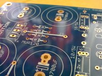
I see that many builders have used wire for the jumpers J1, J2 and J3, but is it really necessary? Upon closer inspection (and measurement) of the pcb I realized that J1, J2 and J3 are already made via a circuit track. Is it worthwhile to add a wire parallel to the existing track to (maybe) create a lower impedance path for the return-current?
Attachments
Where is the 17V? On filter caps? Or is your AC? How much is the DC on filter caps?
Hi Salas;yes its 17v ac and I have 22v dc on the caps. All other voltages are ok. I have had it running for a few hours and nothing overheats so I guess the extra 2v is not a problem.
There is something a little confusing about this Blue board. Look dead center where the 10 LED's are installed (5 LED's per rail). It seems that the flat back corresponds with the cathode or shorter lead of the LED. I also noticed that the LED's have a square hole side and a circular hole side. You'll see that the square hole for the 3 LED/rail section corresponds with the cathode, but this doesn't seem to be true for the 5 LED/rail side. So is the pictograph of the LED accurate or is it the hole shape that is accurate to designate which way the LED's should be mounted?
Anand.
Anand.
I followed the pictograph. You are correct on the 3led and 5led the pads are switched.
Last edited:
I would prefer it taps from TX to its own rectification and filter.
Report Post Reply With Quote
Salas,
Going to go this route for now until I get a second TX, if it sounds ok like this might just keep it as is.
Before I go ahead with this, My TX has 2 sec windings. I will use one of the windings for the teddy but do I have to put some kind of load via a resistor for the other winding or not? I guess, my question is whether or not putting the teddy on the one side of the tranny will affect it in any way due to the extra draw of power from the teddy.
Thanks
- Home
- Source & Line
- Analog Line Level
- Salas hotrodded blue DCB1 build