Hey dudes.
I want to replace the multi-section electrolytic capacitors in an old Dyna SCA35 amp, but their values are non-standard. I was wondering if you recommend going higher or lower than the original values.
The originals are 50 + 50 µF, and 60 + 40 + 20 µF, all 450 V.
What do you recommend I put instead? I've seen something called the EFB mod, which uses 47 + 47 µF and 120 + 120 + 120 µF. These values are considerably higher than stock, but also uses different PSU circuit. I will not be using this "EFB" circuit. Can I still copy these capacitor values while keeping everything else stock?
The amp uses regular diodes for rectification, with EL84 tubes in push pull and can supposedly output about 17 watts per channel.
Thanks dudes. 😉
Last edited:
The original Dynaco SCA35 circuit is rated at 17.5 Watts per channel, but will only meet that rating under limited conditions. Testing has shown that it will not come close to that when both channels are driven simultaneously.
Dave Gillespie’s simple and very inexpensive EFB mod will allow the amplifier to meet or exceed that rating with both channels driven, and at lower distortion. His original article showed no changes or “mods” to the power supply circuit, and the original power supply filter capacitors were reused, as I recall.
For what it’s worth, electrolytic capacitors of that era often had a tolerance of -50%, +75 or 100% of their listed capacity. That should give you some idea of the range you should look for, if you decide to replace the cans. New capacitors usually run much closer to the advertised rating.
The original solid state rectifiers were only rated at 500ma., since larger ones were more expensive at the time. I’d recommend replacing them with 1 Amp UF4007’s, regardless of any other changes you decide upon. I use 3 Amp “Ultrafast” rectifiers (sold under various part numbers) at a cost of about $.35/each.
UF4007s or, even better, Cree C4D02120A 1200 PIV Schottkys.
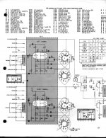
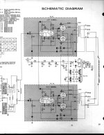
It always pays to peruse the schematic, which I've uploaded.
As modern 'lytics are much more volumetrically efficient than the OEM parts, increasing the capacitance in the PSU filter and decoupling positions is easy enough. Play safe and install a CL-130 inrush current limiting thermistor between the junction of the rectifying diodes and the PSU filter.
The 7199 small signal tri/pent is a problem. The type has gone the way of the Dodo (extinct). Other tri/pent tubes that are electrically suitable are out of production and supplies are fast dwindling. FWIW, I suggest you buy replacement ST35 PCBs and "ditch" the crappy tone controls.
A RC bias network in each channel eases replacement O/P tube matching requirements. Pairs are EASIER to source than quads.
If you listen to vinyl, we can discuss the phono section.
Attachments
I wouldn't get too carried away with large increases in supply capacitance despite the obvious sonic benefits because the power transformer in the SCA-35 is running right on the hairy edge of self-immolation. (I've seen a few fried even with the stock capacitor values) Larger capacitors will increase the peak current flowing in the HV secondary significantly and the additional heating in that winding might be enough to push it over the edge. I wouldn't go more than 20% or so higher in value at most.
I wouldn't get too carried away with large increases in supply capacitance despite the obvious sonic benefits because the power transformer in the SCA-35 is running right on the hairy edge of self-immolation.
This is unfortunately true and I have never seen it stated in print before. I fully rebuilt a SCA-35 and was shocked to find the power transformer so hot after an hour that it was impossible to touch it. I measured 168mA current (10 ohm resistor right after the diodes) at quiescent and 208mA just before clipping, both channels driven. I assumed the 50 year old transformer was defective so bought a new replacement intended for the SCA-35. It is rated at 180mA and after an hour's use this transformer is just as hot as the original. I now use the amp for an hour at a time. A friend pointed out that these amps have survived 50 years with these power transformers, so all must be well. I still have visions of my equipment rack erupting in a conflagration every time I use the amp....
How about converting the PS to dual mono as the trans. are affordable and it should help the sonics as you will have greater headroom. Maybe lower cost toroid would fit for the second one or use 2 as matching may be difficult.
I have Eico HF-12's and those PS sure run hot also and so I have used a cheap fan hooked up to a light dimmer to slow it down for quietness. touchable now and should help lifespan.
I have Eico HF-12's and those PS sure run hot also and so I have used a cheap fan hooked up to a light dimmer to slow it down for quietness. touchable now and should help lifespan.
Last edited:
If the mechanical fit is good, changing power transformers is an idea that has definite merit. A strong case has been made for the Z565 being the best of the Dyna O/P "iron".
AnTek's AS-2T300 seems to be a possibility. While the nominal secondary voltage is less than the Dyna OEM part, the toroid will definitely droop LESS under load. Plenty of filament current is present too, which allows for the addition of DC heating in the phono section.
AnTek's AS-2T300 seems to be a possibility. While the nominal secondary voltage is less than the Dyna OEM part, the toroid will definitely droop LESS under load. Plenty of filament current is present too, which allows for the addition of DC heating in the phono section.
I want to keep the amp as close to original as possible, with the exception of new components of same value (resistors and capacitors). At present it doesn't work right (sounds horribly distorted) and I assume new tubes will fix that, but I'm putting in new caps and resistors while I'm at it, since there are so few of them. The original resistors are carbon composition, right? Can't have that.
Poor ventilation in both the ST35 and the SCA 35 exacerbates the “hot” transformer issue. While the ventilation is marginal in the ST-35, it is poor in the enclosed chassis SCA35. The ST-35 usually holds up to the hot conditions, however the SCA’s will burn out the power transformer from time to time.
A relatively simple solution to reduce transformer temperature, is to use an outboard heater supply, since the heaters draw 25% of the power consumed by the amplifier. Doing so will result in a noticeably cooler running transformer, prolonging its life.
Unique Tube Heater Supply
A relatively simple solution to reduce transformer temperature, is to use an outboard heater supply, since the heaters draw 25% of the power consumed by the amplifier. Doing so will result in a noticeably cooler running transformer, prolonging its life.
Unique Tube Heater Supply
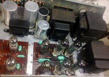
I have increased the capacity of the capacitors to ~ 800mkF.
But even using the throttle. Diodes UF4007.
The transformer has a strong heating power but it works for 5-8 hours a day. The transformer is reliable, we have the frequency of 50Hz, and this is an additional overload.
But even using the throttle. Diodes UF4007.
The transformer has a strong heating power but it works for 5-8 hours a day. The transformer is reliable, we have the frequency of 50Hz, and this is an additional overload.
Attachments
What's mkF? Milli-kilo-farad? I cannot understand that. 🙂
What's that extra transformer in there for?
What's that extra transformer in there for?
800uFWhat's mkF? Milli-kilo-farad? I cannot understand that. 🙂
What's that extra transformer in there for?
An inductor, a choke
http://www.diyaudio.com/forums/tubes-valves/71300-photo-gallery-667.html
post 6663
For the sake of completion, I would like to replace the 95 ohm 5 watt resistor in the PSU, but my sources do not carry this value. What would be a better choice - 100 or 91 ohm? I've read that 100 ohm would be easier on the tubes, but result in lower possible power output. True?
If both are poor options, I'll leave the original alone.
If both are poor options, I'll leave the original alone.
For the sake of completion, I would like to replace the 95 ohm 5 watt resistor in the PSU, but my sources do not carry this value. What would be a better choice - 100 or 91 ohm? I've read that 100 ohm would be easier on the tubes, but result in lower possible power output. True?
If both are poor options, I'll leave the original alone.
Either should work. I'd expect the line voltage fluctuations to have more effect than 5 ohms here.
The 95 ohm resistor is not part of the power supply, although it kinda’ looks that way, because of the way it‘s positioned in the schematic. This resistor is the cathode bias resistor which sets the current in all four output tubes. It is a 5% tolerance resistor which means that everything from 90.25 ohms to 99.75 ohms is in “spec”. If it’s not damaged, or charred, I’d use it. It’s a wire-wound resistor which rarely changes value or fails. The available values you mentioned will realistically have only a minor effect on tube life, and even less on power output.
Reusing this “stock” configuration, does however, mean that a carefully matched “quad” of output tubes is a necessity.
Reusing this “stock” configuration, does however, mean that a carefully matched “quad” of output tubes is a necessity.
The before mentioned EFB mod will cool things down and solves the resistor question (besides helping the sonics), as it allows the output tubes to run cooler helping their life. You can also set up this mod for individual adjustment of each output tube also as a further benefit as you don't need carefully matched tubes.
Dave's Lab
There should be room to add a second PS trans which should further help the sonics along with cooler running (if there isn't maybe mount it at the back of the amp on a small chassis or enclosure)
All the above are reversible and the unit isn't rare anyway.
Dave's Lab
There should be room to add a second PS trans which should further help the sonics along with cooler running (if there isn't maybe mount it at the back of the amp on a small chassis or enclosure)
All the above are reversible and the unit isn't rare anyway.
Last edited:
if i were to redo the power traffo for this amp, i would do it as a full wave doubler, lower voltages, lower dc resistance on secondary windings....
At present it doesn't work right (sounds horribly distorted) and I assume new tubes will fix that, t.
The Dyna needs a matched set of 4 output tubes, because of the shared cathode R/C parts. To be able to use two matched pairs instead,
separate the cathode circuit R42/C24 into one for each channel. Use a resistor of twice the value, and a capacitor of half the value (or more).
Connect each filament hum pot wiper to its own channel.
I already have a matched quad waiting for it, and this seems to be the cheapest route when buying (brand new, not NOS) EL84 valves (I got them for about 30€), so I don't think this is a problem. But if I were to do this, I would need to put two 47 µF caps, two 180-200R resistors (as opposed to the original 100 µF / 95R arrangement)?
To clarify: I do not want to keep it stock due to me thinking it's some sort of collector's item, but because its appearance (internal and external) appeals to me a great deal, and I've never even listened to the amp, so I would like to hear it in its "original" glory before possibly jumping into modding territory.
- Status
- Not open for further replies.
- Home
- Amplifiers
- Tubes / Valves
- Safe PSU capacitor values for old Dyna amp?