I've purchased this amp as a basket case; it was missing outputs, top cover, and a choke assembly on one channel on the main amp board. Luckily it was not molested too much.
My problems are I am getting 40.1vdc measuring bias across Q13,14 collectors, Bias pots have no effect (should be 2.1vdc here). Relay doesn't click with outputs installed (did click without them) and dc offset measured @ the 0.125 resistors is -750mv channel B, -1.7 to -3.1 volts DC (erratic) channel A. offset pot has no effect on channel A. I've replaced the bias IC on a guess with CA3086 NOS from ebay but has no change. I've tested the bias ICs and I think they're all good. Also I was advised to short collectors of Q9,10 to eliminate the bias IC from the equation and still no effect. So its not the bias IC.
Here's what I've been doing so far:
I've installed all new outputs
MJ11021 for SAE204 (11-0070)
MJ4502 for SAE202 (11-0069)
MJ802 for SAE101 (11-0063)
MJ11022 for SAE103 (11-0064)
according to wardsweb.org these are appropriate equivalents.
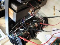
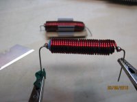
hand made new choke assembly on a 2.2ohm wirewound resistor and wrapped with magnet wire. It is an exact replica of the original.
made CAD drawing to have a new cover fabricated.
on the main amp board the SAE301 (11-0075) diodes were replaced with a Motorola part # and installed backwards by someone else. They were also shot. Replaced them with IN5820. Replaced the IN4004 diodes on this board with new al well. Both 1.2ohm resistors to ground on this board were shorted, since been replaced.
On channel A driver board driver transistor NPN 2N6316 was replaced with a sony D291 (still tested good) but I through in a new 2N6316. The 1.2ohm resistor to ground was bad here as well and since been replaced.
I've recapped both driver and main amp board completely and replaced any carbon resistors with metal film.
@ the 51v zener diode on driver board I am getting 49.8v channel A, 50.1v channel B using dbt.
My problems are I am getting 40.1vdc measuring bias across Q13,14 collectors, Bias pots have no effect (should be 2.1vdc here). Relay doesn't click with outputs installed (did click without them) and dc offset measured @ the 0.125 resistors is -750mv channel B, -1.7 to -3.1 volts DC (erratic) channel A. offset pot has no effect on channel A. I've replaced the bias IC on a guess with CA3086 NOS from ebay but has no change. I've tested the bias ICs and I think they're all good. Also I was advised to short collectors of Q9,10 to eliminate the bias IC from the equation and still no effect. So its not the bias IC.
Here's what I've been doing so far:
I've installed all new outputs
MJ11021 for SAE204 (11-0070)
MJ4502 for SAE202 (11-0069)
MJ802 for SAE101 (11-0063)
MJ11022 for SAE103 (11-0064)
according to wardsweb.org these are appropriate equivalents.
hand made new choke assembly on a 2.2ohm wirewound resistor and wrapped with magnet wire. It is an exact replica of the original.
made CAD drawing to have a new cover fabricated.
on the main amp board the SAE301 (11-0075) diodes were replaced with a Motorola part # and installed backwards by someone else. They were also shot. Replaced them with IN5820. Replaced the IN4004 diodes on this board with new al well. Both 1.2ohm resistors to ground on this board were shorted, since been replaced.
On channel A driver board driver transistor NPN 2N6316 was replaced with a sony D291 (still tested good) but I through in a new 2N6316. The 1.2ohm resistor to ground was bad here as well and since been replaced.
I've recapped both driver and main amp board completely and replaced any carbon resistors with metal film.
@ the 51v zener diode on driver board I am getting 49.8v channel A, 50.1v channel B using dbt.
Last edited:
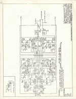
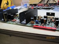
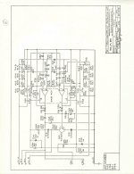
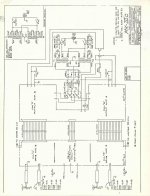
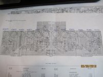
schematic & some pics
not sure where to go from here, if anyone has any suggestions I'd really appreciate it.
not sure where to go from here, if anyone has any suggestions I'd really appreciate it.
Attachments
-
 mkiiicm_d.jpg246.1 KB · Views: 317
 -
 045.jpg452.7 KB · Views: 154
 -
 047.jpg460.9 KB · Views: 279
 -
 043.jpg443.4 KB · Views: 285
 -
 040.jpg543.4 KB · Views: 308
 -
 034.JPG928 KB · Views: 300
 -
 mkiiicm_d_zpsamtykgj9.jpg220.7 KB · Views: 183
 -
 mkiiicm_a_zps6rxlkgjg.jpg165.6 KB · Views: 149
 -
 mkiiicm_c_zpsjv6mukgd.jpg176.7 KB · Views: 150
Last edited:
You should have 50 volts across the collectors of Q13/14, the manual is wrong, the schematic is correct. The approx. 2.1 volts will be across the bases of Q13/14 OR the collectors of Q9/10. The manual should have you measuring the collectors of Q9/10 as they are easier to get to.
Have you tried using the troubleshooting guide in the manual? You'll have to be able to recognize the errors in it though.
Go back and check all of your work. Diodes, transistors, capacitors all installed correctly and the their proper location?
Craig
Have you tried using the troubleshooting guide in the manual? You'll have to be able to recognize the errors in it though.
Go back and check all of your work. Diodes, transistors, capacitors all installed correctly and the their proper location?
Craig
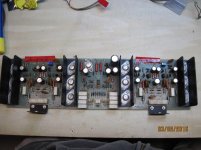
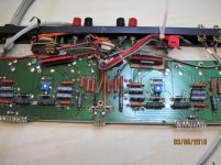
Looking at the picture of the output PCB you have the big Schottky diodes installed backwards. The anodes go towards the + rail and cathodes go towards the - rail, in other words forward biased. The flyback diodes, D14/15, are just the opposite, reversed bias. They appear to be installed correctly.
Also note the PCB is NOT laid out in mirror image. Make sure anything polarized is installed correctly, diodes, electrolytics, etc.
Craig
Also note the PCB is NOT laid out in mirror image. Make sure anything polarized is installed correctly, diodes, electrolytics, etc.
Craig
What's the value of the two resistors next to the connector pins? Should be 62 Ohms, I can see the blue stripe but that's it. I would expect to see blue, red, black, gold or maybe blue, brown, white, gold on those Dales.
Craig
Blue, gray, black, brown? 6.8k Ohms?
Craig
Blue, gray, black, brown? 6.8k Ohms?
Last edited:
funny you mention that. I was just removing them, it's the first thing I thought of that could be wrong, except I thought I had Q13, 12 backwards. I was following a pcb printout I have instead of the schematic. Print-out may have some errors, R38 is listed as 68ohm which is what I put in.
Q12,13 (SAE301) are the IN5820 big Schottky diodes. Anode towards + rail. you mean these are backwards?
Q14,15 are the IN4004
Q12,13 (SAE301) are the IN5820 big Schottky diodes. Anode towards + rail. you mean these are backwards?
Q14,15 are the IN4004
Attachments
I've purchased this amp as a basket case; it was missing outputs, top cover, and a choke assembly on one channel on the main amp board. Luckily it was not molested too much.
My problems are I am getting 40.1vdc measuring bias across Q13,14 collectors, Bias pots have no effect (should be 2.1vdc here). Relay doesn't click with outputs installed (did click without them) and dc offset measured @ the 0.125 resistors is -750mv channel B, -1.7 to -3.1 volts DC (erratic) channel A. offset pot has no effect on channel A. I've replaced the bias IC on a guess with CA3086 NOS from ebay but has no change. I've tested the bias ICs and I think they're all good. Also I was advised to short collectors of Q9,10 to eliminate the bias IC from the equation and still no effect. So its not the bias IC.
Here's what I've been doing so far:
I've installed all new outputs
MJ11021 for SAE204 (11-0070)
MJ4502 for SAE202 (11-0069)
MJ802 for SAE101 (11-0063)
MJ11022 for SAE103 (11-0064)
according to wardsweb.org these are appropriate equivalents.
hand made new choke assembly on a 2.2ohm wirewound resistor and wrapped with magnet wire. It is an exact replica of the original.
made CAD drawing to have a new cover fabricated.
on the main amp board the SAE301 (11-0075) diodes were replaced with a Motorola part # and installed backwards by someone else. They were also shot. Replaced them with IN5820. Replaced the IN4004 diodes on this board with new al well. Both 1.2ohm resistors to ground on this board were shorted, since been replaced.
On channel A driver board driver transistor NPN 2N6316 was replaced with a sony D291 (still tested good) but I through in a new 2N6316. The 1.2ohm resistor to ground was bad here as well and since been replaced.
I've recapped both driver and main amp board completely and replaced any carbon resistors with metal film.
@ the 51v zener diode on driver board I am getting 49.8v channel A, 50.1v channel B using dbt.
I have to concur with Craig as i look at that 3 section driver board. It seems odd the diodes would go the same way and I realize that not having screening on the board is a PITA but you should be able to figure it out with your ohmmeter where these components connect on both sides.
It is not uncommon for bias pots to open in SS amps.I typically set the bias for a change in current like McIntosh does in their setups after setting the bias at minimum..You can't do it this way on all amps but I have done this on Ampzillas and other GAS amps with great success..
Have you measured the base to emitter on each of those transistors so its at least .5 to .7 vdc. This can tell you in which area the problem may exist.Keep the outputs out when you do this but you may just find which area is the culprit.
One more thing and this is for later..Putting in all metal film resistors is going to compress the sonic nature this amp is so famous for..Put in 3% Carbon films especially on the base where the signal comes in and maybe use non inductive wirewounds on the collectors..I use CC on the base that are measured within tolerance because you want that wide bandwidth and CC resistors are non inductive.
The schematic says 62 Ohms, I didn't think anything of it as James used this value in this position in many of his designs. If 68 Ohms was in it that's fine, that's what is in the parts list and locator diagram.
Not having silk screening makes things a bit more difficult especially when the service manual is wrong as the arrows on the Schottkys are backwards on the component location diagram.
Ds NOT Qs. The 1N4004s appear to be installed correctly, the 1N5820s are backwards. You can leave them out for now as the amp will run fine without them.
Craig
Without a reference that voltage is meaningless. That voltage should be 1/3 of the total B+/-. If your B+/- rail is 60VDC then what you are measuring is correct. Check the voltage on the collectors of Q16/19, should be about 40VDC referenced to gnd. Your actual B+/- should be +/-75VDC without the DBT and 120VAC input. At full line voltage you should have +-75VDC, 50VDC and 25VDC on the appropriate collectors.
Provided all of your parts are correct and in the correct location I doubt your bias and DC problems are in the output stage. Also if you think that voltage will change with the bias setting it will not, you need to look further upstream. Concentrate on the collector voltage of Q9/10, that's the voltage the bias will change.
Craig
Just thought of a couple things I keep forgetting to ask you,
1. Are you trying to troubleshoot with both channels powered at the same time? If so yank the fuses on one channel and troubleshoot the other. The DBT will have more meaning that way.
2. Are there a small aluminum shims between the bias ICs and the heatsink? If there aren't, the MKIVD does have them, make sure the ICs are in contact with the heatsink. Spread some thermal compound on the IC and set the heatsink on and then remove, did the compound transfer? If it didn't you need shims.
Craig
bias ICs do have the shims on the heat sink.
I was tryin both channels at once, I'll pull the fuses and still with channel B for now.
@ Q9/10 across collectors I'm getting around 300mv but it fluctuates from 300ish up around 1v then back down every second or so. I know all the TO-66's are good gotta be one of the smaller components on driver board.
I'm back at it. Didn't quit, just got busy with life ****. Though I was a bit discouraged, it's just a power amp it cannot be that complicated.
To answer your question craig the bias ICs are in contact with the heatsink and have grease on them. And at the moment I'm still too pussy to attempt a full voltage power up, but I might just say **** it and try it later tonight.
I have some readings, everything is looking good using DBT.
Rail voltage on driver board:
channel B 59.5vdc, -59.8vdc
Channel A -58.7, 58.5vdc
taken @ the 10 ohm resistor. Schematic calls for (+-)74.8vdc
Rail voltage on main amp board:
Channel B 59.5vdc, -59.8vdc
Channel A 58.8vdc, -59vdc
taken at the 1.4kohm 5 watt resistors
Channel B
Q19 -40vdc
Q16 40vdc
Channel A
Q19 -39.9vdc
Q16 39vdc
to proceed, I tried removing the fuses. With fuses out on channel A I do get relay click. With fuses out on channel B I do not get any relay action.
Channel A has the high dc offset (-2.2vdc) and had the oddball sony driver and 1.2ohm resistors to ground shorted. This must be the problem channel (B)
with fuses out on channel B, just focusing on channel A right now.
channel A
My bias is 115mv (unable to adjust at all with bias pot.
dc offset around -15mv
(done with dbt)
Last edited:
with fuses out on channel B, just focusing on channel A right now.
channel A
My bias is 115mv (unable to adjust at all with bias pot.) across Q9/10
dc offset around -15mv
(done with dbt)
At full voltage just channel A
115mv bias across Q9/10
Rail voltage
At 1.4kohm resistors (+-)76vdc
at 10 ohm resistors +75.7vdc, -74.5vdc
this bias nonsense is driving me nuts. wtf is going on
Last edited:
out of frustration, I removed the driver board and ran though channel A pulling leads and components checking everything.
all resistors & diodes are good
I found that Q55/Q56 (Q5/6 on channel B schematic) were replaced with a PNP 9003 transistor on channel A. Channel B has the 2N4250 installed that's listed in the schematic (edit: schematic actually has a 2N4249). While my pcb printout lists a BC307B part # and indicates this is a matched pair. These 9003 transistors did test good, any idea if they're an adequate sub?
The Q53/54 2N3565 tested funky on my peak tester indicating darlington which they are not, mm diode test doesn't show continuity. pcb printout lists a BC237B for part #.
Q57 SAE904 is short at collector. wardsweb lists MPSA92 here which bdent has available.
giving the confusing difference in part numbers, Dose anyone know the BC237/BC307 are good subs for 2N3565/2N4250? It would mean I can order new parts from bdent.com vs buying nos off ebay......went with the bdent.com order
This is all channel A stuff. I'm sure there's something still ****** in channel B. I will go through that channel next checking the same parts.
Last edited:
parts order came in
on channel A I subbed Q7 SAE904 (shorted) with an MPSA92.
Subbed Q5,6 with BC307 and gain matched them. These transistors tested ok but were previously replaced with transistors labeled 9003 and nothing else. They're not original and I didn't trust them.
power up with dbt channel A only; now I have a relay click, set bias at 2.1v across Q9,10 and set the offset. Finally some success.
I will checkout and replace the same transistors on Channel B. I also have replacements for Q3,4 BC237B if need be.
Well what do you know channel B had the same Q7 SAE904 transistor shorted. Replaced that with MPSA92 and replaced the Q5,6 with BC307 just to avoid future issues. Gain matched the new pair.
Running at full power both channels; relay operates and bias is set @ 2.1vdc channel A, 1.968vdc channel B is the highest I can set it. Should be 2.1vdc each channel. Going to take a look at output into 8 ohms and look for distortion with scope.
Running at full power both channels; relay operates and bias is set @ 2.1vdc channel A, 1.968vdc channel B is the highest I can set it. Should be 2.1vdc each channel. Going to take a look at output into 8 ohms and look for distortion with scope.
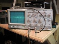
ran the outputs into 8 ohm load 1khz sine wave channel A seemed ok putting out 98wrms. I'm just using a laptop program signal generator that does not put adequate input voltage to reach full power.
Channel B was not working properly. Showing picture if that helps. But will likely be taking another look into driver board B.
Channel B was not working properly. Showing picture if that helps. But will likely be taking another look into driver board B.
Attachments
- Status
- This old topic is closed. If you want to reopen this topic, contact a moderator using the "Report Post" button.
- Home
- Amplifiers
- Solid State
- SAE Mark IIIC - Repair Help