I am working on a SAE 202.
The heat sinks are ice cold and I am stuck. I cannot get the unit to bias correctly.
I had to remove the output transistors on one channel due to a stupid mishap.
I know what I did. It was dumb and I can correct it. Just putting that out there and this may tie into my main problem.
I was probing the input board and saw voltages that feed the bias pot all over the place. By coincidence I blew on a 2sk333 differential amp and I saw the voltages by the bias pot fly all over the place. I repeated it with a drinking straw and if I puffed the slightest amount of air across that device it would create some incredible voltage swings. I was not blowing any air near the bias diode on the heat sink. It was very directed air. I never saw anything like this happen before! And it was almost instantaneous. It only took a puff of air to make it go crazy.
I replaced both 2sk333's and now I don't have the crazy voltage swing BUT I do have very high voltages at the base of the driver and the base pads for the output transistors. The voltage is just about near rail voltage.
What type of voltages should I be seeing at the bases of the driver and output base pads? There is a NegFBack line feeding back to the input board. Could the absence of the output transistors be causing the bias voltages to go so high?
I am lost and need some help. I really don't want to reinstall the output transistors only to watch them vaporize from an insane bias voltage. Any help is greatly appreciated.
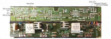
I don't have schematics for the amp but I did create the following to help me trace signal paths. I did invert the top portion so the traces match component placement. It seems easier for me this way. PS. I do plan on cleaning up those crusty pads 🙂

The heat sinks are ice cold and I am stuck. I cannot get the unit to bias correctly.
I had to remove the output transistors on one channel due to a stupid mishap.
I know what I did. It was dumb and I can correct it. Just putting that out there and this may tie into my main problem.
I was probing the input board and saw voltages that feed the bias pot all over the place. By coincidence I blew on a 2sk333 differential amp and I saw the voltages by the bias pot fly all over the place. I repeated it with a drinking straw and if I puffed the slightest amount of air across that device it would create some incredible voltage swings. I was not blowing any air near the bias diode on the heat sink. It was very directed air. I never saw anything like this happen before! And it was almost instantaneous. It only took a puff of air to make it go crazy.
I replaced both 2sk333's and now I don't have the crazy voltage swing BUT I do have very high voltages at the base of the driver and the base pads for the output transistors. The voltage is just about near rail voltage.
What type of voltages should I be seeing at the bases of the driver and output base pads? There is a NegFBack line feeding back to the input board. Could the absence of the output transistors be causing the bias voltages to go so high?
I am lost and need some help. I really don't want to reinstall the output transistors only to watch them vaporize from an insane bias voltage. Any help is greatly appreciated.
I don't have schematics for the amp but I did create the following to help me trace signal paths. I did invert the top portion so the traces match component placement. It seems easier for me this way. PS. I do plan on cleaning up those crusty pads 🙂
Attachments
Normally I'd jump right in on an SAE repair but this model is an "off shore" SAE that I don't have much experience with. I do have the schematic for the A502, not sure if it will help or not. PM me with your email address and I'll send it to you.
Craig
Craig
I think you should have approx. 2.4VDC between the bases of the drivers, that would put the bases of the outputs at approx. .6VDC, just turned on.
Craig
Craig
..this model is an "off shore" SAE that I don't have much experience with. I do have the schematic for the A502, not sure if it will help or not.Craig
Thank you for the offer Craig. I also have a good copy of the 502 schematics. While the 502 and 202 are from the same family and share a few component similarities, the board layouts are quite different. The 502 has some more advanced auto biasing and no bias pot. The 202 has manual biasing with a bias pot.
2.4 volts on the base with respect to ground, correct?
Thanks!
2.4VDC base to base.
Craig
Got it!
Hopefully I can spend a little time looking over it this evening.
I have a server project at work that leaves me dragging home and falling asleep. If I find anything I will post my findings.
Thanks again!
I realized I left this thread sort of hanging with no conclusion.
So here is the condensed version.
I really wanted to understand what was going on with this amp, not just fix it.
So I painstakingly reverse traced the entire amplifier assembly and created a working virtual model of it in SpiceLT. This included both the input board and amplifier boards.
I never used circuit simulation software before so there was a learning curve there. I got the main gist of it learned over a weekend.
As a reminder there are no known A202 specific schematics available. There are schematics for the larger A502 which does biasing temp compensation differently.
Now I have the entire schematic drawn by my own hands. With that in hand I could compare virtual voltages to the real voltages on the physical unit.
The root cause of the problem was a resistor that had wandered way out of spec. I had to pull that resistor out of the circuit to discover that.
I also upgraded the Toshiba output transitors to Sanken equivalents. The Sankens are slightly larger and have higher current capability but match the rest of specs.
I learned quite a bit from this amp and I have a better grasp of what is going on, at least with this design.
As you say, there is no known schematic and you've just done the hard lifting and produced one in LT spice, I think. Would it possible to share the asc file here? Within file size limits, attaching a file is a lasting way to do this, since image hosts tends to be forgotten and the files lost. I don't have the need but it's certain there are others who'd like to get their A202 repaired and working again.
As you say, there is no known schematic and you've just done the hard lifting and produced one in LT spice, I think. Would it possible to share the asc file here?
My intention was to eventually make this schematic available to the public. That's what these forums are all about. I would love to see the SAE gear hidden in closets come out and play. The drawing is functional but not complete. I really want to improve on the drawings as I have free time. In my drawings I am using a virtual power supply source generated by LTSpice. I would like to actually draw out the physical power supply board and distribution/safety board as well.
I had to make some assumptions for my learning process and omit small parts of the DC protection circuit, just leaving the bare amplifier topology.
The component values have all been entered but the location numbers have to be updated.
I am a little weary of posting any schematic of a former production piece on a public forum to respect any intellectual property rights and forum rules. However if anyone needs the drawing as it currently stands, I will gladly provide it if they contact me via PM. I can provide a Spice file or generate a PDF of the drawing.
In the early models of A202, all three of R201,202,203 are 100 ohm. With bias adj pot(VR201) of good condition(470 ohm VR) I could get around 15-20mV bias voltages across R213 and slightly warmed up heat sinks. The later models of A202 has R201 of 4.7 ohm, R202&203 of 3.3 ohm. The value of VR is the same 470 ohm. It's heat sinks remained literally ice cold and bias could not be adjusted. I think VR of 470 ohms with 3-4 ohm R201-203 is faulty combination. After I replaced all three of R201,202,203
to 100 ohm, I could get good results as in older A202, proper values of bias voltages, slightly warmed up heat sinks and good sounds.
to 100 ohm, I could get good results as in older A202, proper values of bias voltages, slightly warmed up heat sinks and good sounds.
Looking for help with an old SAE MK 31B. I had an issue with the amp in which an output transistor and a couple of the matched input transistors failed. I ended up rebuilding it with original genuine SAE parts including matched input transistors & capacitors. After completion the amp has a slight low tone hum and was wondering if it needs a bias adjustment. I am not not an expert on this type of thing and was looking for input.
- Home
- Amplifiers
- Solid State
- SAE Bias Problem