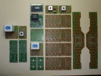
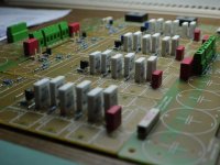
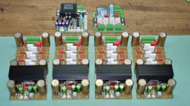
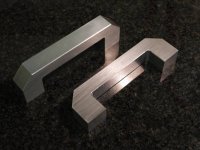
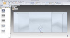
Motivated by Toni´s thread in the Solid state forum I finally show a series of images of a huge 4-channel amp based on the Texas Instruments LME49830 input stage chip. The circuit schematic and the circuit boards for this amp were designed by Astx. He was so kind to present a whole set of boards as well as several parts and one programmed micro-controller to me! Thanks again Toni, very generous! So I simply had to build this amp.
Attachments
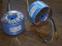
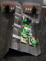
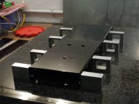
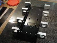
These were the Pcb´s and 550 VA transformers and I even managed to find a suitable heat sink. My idea was a steel backbone for the amp which would make wiring and assembling easier and as well offer some advantages for wiring too.
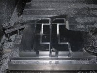
Here the build in the first stages with the U-channel steel part.For the transformers I made mild steel tubes out of sheet metal for shielding and better optics. The top covers are stainless steel.
Here the build in the first stages with the U-channel steel part.For the transformers I made mild steel tubes out of sheet metal for shielding and better optics. The top covers are stainless steel.
Attachments
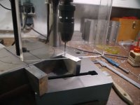
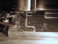
The new drill press in use. At the sides of the U-channel I mounted thick aluminum parts which form well separated, additional shielded channels. These are located under the capacitor banks. In these channels the input cables and some low voltage cable are routed. This layout made wiring very easy and AC, DC and signal carrying cables are very well separated. This prevents unwanted EMI induction.
Attachments
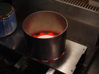
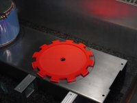
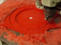
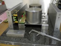
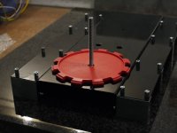
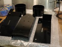
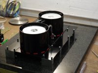
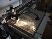
On my small CNC I milled base plates for the transformers out of thick red plastic sheet. These plates are shaped in a way to allow air flow on the inside of the shielding steel tube cooling the transformer. Of course, the covers are mounted with a proper spacing to let the air escape on top. Below the plastic there is the white damping rubber visible.
Attachments
Making the electronics often is the easiest part of a build, this one was truly enjoyable!
Attachments
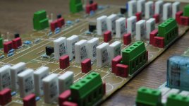
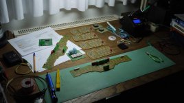
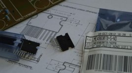
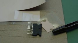

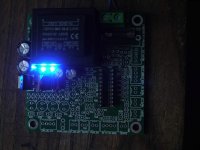
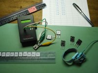
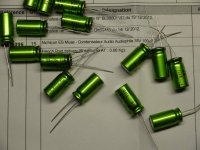
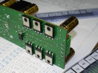
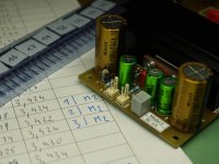
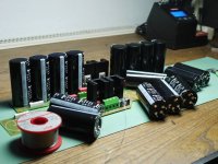
Checking the power supply of the “housekeeping” board. MOSFET´s were measured and numbered for selection. Some fine capacitors arrived from France and Canada.
Attachments
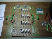
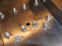
With the stuffed boards I could check back with the chassis and look for mounting problems. The studs were soldered onto the chassis. This is not a good idea if you plan to get the chassis powder coated. There is the possibility that the solder melts at the curing temperature of the coating.Good that I mentioned it and the powder coating company could lower the temperature somewhat for me.
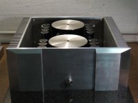
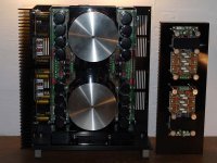
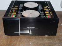
The last picture shows that it will be a real power station…
The last picture shows that it will be a real power station…
Attachments
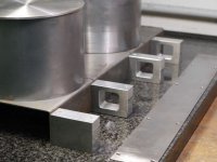
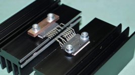
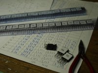
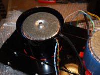
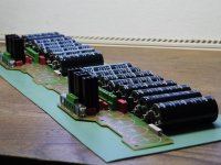
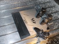
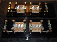
At last I soldered the MOSFET´s into the modules. A heavy amp requires good grips and my CNC-milled ones are doing the job.
Attachments
-
 47 2 Module fertig.jpg117.9 KB · Views: 235
 -
 46 MosFet eingelötet.jpg98.2 KB · Views: 219
 -
 45 Modul 2 fertig.jpg96 KB · Views: 164
 -
 44 gematchte MosFets.jpg108.6 KB · Views: 190
 -
 39 Fräsen.jpg84.3 KB · Views: 206
 -
 40 fertig gefräst.jpg142.7 KB · Views: 182
 -
 41 Griffe für die Rückseite.jpg99.1 KB · Views: 168
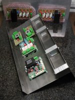
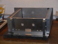
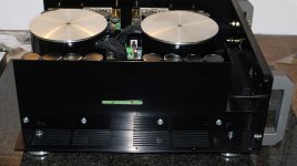
Meanwhile the chassis parts came back from powder coating and another fun part -the actual assembly- could start. I would have chosen a matte finish but unfortunately it was not offered. In the end the glossy black looked good too. The last image shows the rigid backbone of this chassis. In case someone like making a similar chassis, I strongly would recommend using a precision industrial-made U-channel profile and weld in one or two stiffener sheets against torsion forces.
Attachments
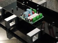
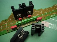
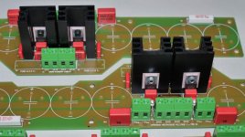
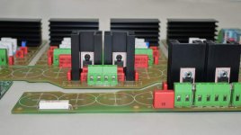
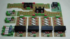
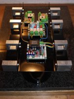
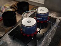
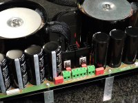
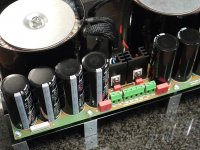
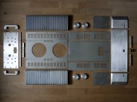
Mounting of the transformers was followed by the power relay board, the microcontroller board, ground lift boards and mains filter. All these boards are located central in the lower compartment.
Attachments
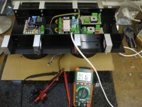
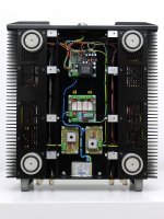
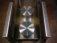
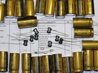
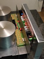
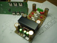
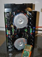
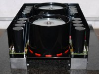
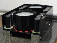
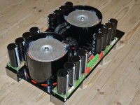
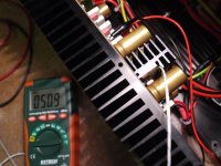
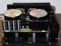
When the big capacitors arrived I could finish the power supply and test it. The voltages were fine. Note the mild steel shielding plates that form an inner enclosure for the power supply. These plates also create a cooling channel for the amp modules. Slots in these plates allow easy wiring.
Attachments
-
 66 Netzteilblock.jpg133.8 KB · Views: 185
 -
 65 Spannungen stimmen genau.jpg124.2 KB · Views: 188
 -
 63 Netzteilmodul fertig.jpg101.8 KB · Views: 149
 -
 62a volle Schrimung.jpg97.9 KB · Views: 146
 -
 62 beide Platinen montiert.jpg143.6 KB · Views: 136
 -
 61 die Kraftwerkszentrale.jpg143 KB · Views: 130
 -
 60 montiert und verkabelt.jpg135.6 KB · Views: 138
 -
 59 Netzteilbau.jpg116 KB · Views: 164
 -
 58 Elkos angekommen.jpg100.5 KB · Views: 168
")
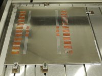
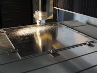
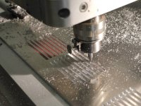
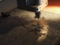
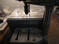
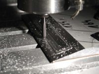
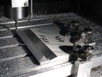
The chassis was finished so far, but there were a lot of parts needed for the enclosure, e.g. a nice top cover with slots. The machine I used was a bit weak, so it took quite a while to make the cover. You can see the orange colored sacrificial material under the aluminum plate, used for protecting the machine´s table while milling the slots.
Attachments
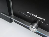
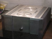
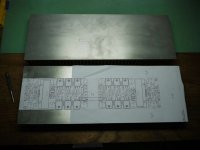
The back plate is not really interesting, more so the front side. It is made of 10 mm thick aluminum and features additional plates making it look more fancy and interesting. The thick plate I obtained from the scrap metal dealer. There are a big number of alloys on the market and it is quite a risk to get a plate that has good properties for anodizing. I know it would work well because I used part of this material before for my Pass F5. These are completely made of scrap aluminum.
Making a good enclosure can be complicated. You may notice that the bottom plate is made out of three parts. The advantage is obvious in pictures of the assembly and wiring.
The parts were anodized by my friends Astx and Wulti. Hard to believe that the anodizing process can be done at home in professional quality, but they succeded!! Economically it does not make sense doing it at home, but it was interesting! No pictures of this witchcraft…
Attachments
-
 87 Status Quo.jpg103.8 KB · Views: 173
 -
 86 Verbohren des Deckels.jpg121.2 KB · Views: 144
 -
 36 Bohrvorbereitung.jpg68.9 KB · Views: 156
 -
 81 Front an Gerät.jpg103.8 KB · Views: 146
 -
 76 Linker Teil fertig.jpg139.1 KB · Views: 128
 -
 75 Schlichten 3m Vorschub, seitl Versatz 0,1mm, 16 min.jpg90.9 KB · Views: 130
 -
 73 25 Schichten zu 0,4mm, seitl. 0,9mm Versatz.jpg121.3 KB · Views: 131
 -
 71 Frontdesign unvollständig.jpg42.1 KB · Views: 150
 -
 70 Rückwand.jpg84.2 KB · Views: 187
 -
 96 ...ready for anodizing.jpg102 KB · Views: 169
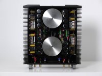
When all the parts were black anodized I could mount the amp modules on the heat sinks. At this time I got another generous gift from a friend -an old Sine Wave Generator (Wien-Brücke Oszillator), laboratory power supplies and a well used Gould oscilloscope. Thanks for this Gerhard!
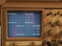
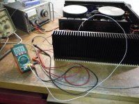
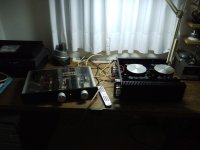
I never had a minute of education in electronics, so I started out reading the manual and setting up a test measure with my F5 monoblock, the image shows a 1 KHz input and output signal. Soon I got the idea how to use this device and I could start testing my SA 2012 amp modules. I made a proper setup and it was a very interesting experience working with a scope.
I never had a minute of education in electronics, so I started out reading the manual and setting up a test measure with my F5 monoblock, the image shows a 1 KHz input and output signal. Soon I got the idea how to use this device and I could start testing my SA 2012 amp modules. I made a proper setup and it was a very interesting experience working with a scope.
Attachments
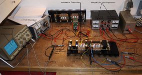
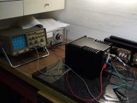
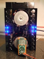
The testing at a low voltage of 15 V was successful and I could mount the modules and connect them to the 70 V of the power supply. A good feeling knowing that the modules are sound and working when the power switch is operated! Now wonder how I could build amps without a scope, it is simply a must!
I could check each module with a 10 KHz sine signal and set the bias, check the heat sink temperature of the amp and the driver IC.
I could check each module with a 10 KHz sine signal and set the bias, check the heat sink temperature of the amp and the driver IC.
Attachments
-
 111 Treiber-IC Kühlkörpertemperatur.jpg130.5 KB · Views: 123
 -
 110 Kühlkörpertemperaturmessung.jpg183.7 KB · Views: 114
 -
 109 Bias einstellen und Funktion mit 10KHz Sinussignal testen.jpg164.4 KB · Views: 128
 -
 108 verkabeln.jpg173.3 KB · Views: 157
 -
 107 ...das Biest wird immer schwerer.jpg130.8 KB · Views: 147
 -
 106 stehende Ansicht.jpg109.2 KB · Views: 110
 -
 105 Schirmblech.jpg82.9 KB · Views: 117
 -
 104 Montage.jpg106.7 KB · Views: 156
Next came a listening test …ahh... the front plate and the cover.
I hope you enjoyed browsing through my pictures. Maybe you find some ideas for own builds, which is something that I encourage you to undertake!
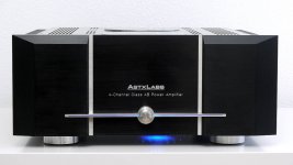
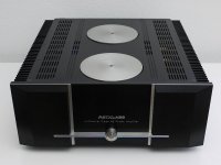
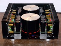
Below you find some product shots and the plots of the distortion measuring of all four channels. Thanks for that too, Toni! The curves and values speak for themselves, I think.
All the best,
Martin
I hope you enjoyed browsing through my pictures. Maybe you find some ideas for own builds, which is something that I encourage you to undertake!
Below you find some product shots and the plots of the distortion measuring of all four channels. Thanks for that too, Toni! The curves and values speak for themselves, I think.
All the best,
Martin
Attachments
- Status
- This old topic is closed. If you want to reopen this topic, contact a moderator using the "Report Post" button.
- Home
- Amplifiers
- Chip Amps
- SA 2012 amplifier - LME49830