Iain,
I just saw your original post. Just a small comment: I used to work as a chip designer, and it did happen from time to time that we used multiple pins for the same internal power. The way we designed things, each power domian was routed in a (once broken) ring just inside the bond pads. From the internal parts we threw in a wire out to the power ring. And from the power rings we would add connections to bond pads here and there, for example in each corner or at other regular intervals.
Separate regulation for separate power domains is great. But separate regulation for two pins on the same power domain could potentially send some destructive current down one pin and up the other.
Cheers,
Borge
I just saw your original post. Just a small comment: I used to work as a chip designer, and it did happen from time to time that we used multiple pins for the same internal power. The way we designed things, each power domian was routed in a (once broken) ring just inside the bond pads. From the internal parts we threw in a wire out to the power ring. And from the power rings we would add connections to bond pads here and there, for example in each corner or at other regular intervals.
Separate regulation for separate power domains is great. But separate regulation for two pins on the same power domain could potentially send some destructive current down one pin and up the other.
Iain McNeill said:A few of my pet must-haves: individual regulators for every IC power pin. (If the chip designer bothered to give us multiple pins, we shouldn't tie them together)
Cheers,
Borge
Thanks for that piece of inside information, Borges. You're right, connecting two regulators together inside an IC is probably not a good thing to do! It pays to read the datasheet eh? The first layout I came up with on the CS8416 had link resistors where I could easily evaluate the benefit of separate supplies. As the design grew to SRC4392, there were too many compromises to justify linking all the power rails. I'll have to build up the supplies one at a time with wire links to evaluate.
Would you say (from your IC experience) that if the pins have the identical name (mnemonic) then they are internally connected but if they have different names then they are different power domains?
Seems like a good convention but a few exceptions would destroy the rule.
Would you say (from your IC experience) that if the pins have the identical name (mnemonic) then they are internally connected but if they have different names then they are different power domains?
Seems like a good convention but a few exceptions would destroy the rule.
Iain McNeill said:Would you say (from your IC experience) that if the pins have the identical name (mnemonic) then they are internally connected but if they have different names then they are different power domains?
Well, given pins "VDDx1", "VDDx2", "VDDy1", "VDDy2", I would join all the x's at one regulator, and all the y's at another.
My personal little hangup is star power. The picture shows one regulator powering multiple opamps that handle related (same-audio-channel) audio data. The layout on the picture minimizes common-impedance noise on the PCB. The output impedance of the regulator will still transform current going to one sink to a voltage drop seen by all sinks. But board will not!
When datasheets say "connect the power pins x and y" I some times make a small power plane beneath the chip. And with multiple chips like that I often use a common regulator and a star. In my present DAC I have one row of regulators for L and one for R.
Remember that with the star, the resistance in the tracks and the local decoupling set up one lowpass filter per IC. So I rarely make those tracks super-narrow.
Cheers,
Borge
Attachments
This Ti chip looks very straight forward to use as receiver for spdif for i2s output, will this circuit work as it is here as an s/pdif reciever with my tda1543 dac board?
unfortunately, the SRC4392 resets into a powered down state. You need a controller to write it's registers over either I2C or SPI.
You also need a master clock but if you're doing a DAC then you probably got a good one of those😎
You also need a master clock but if you're doing a DAC then you probably got a good one of those😎
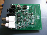
Ahh that brief moment of exhilaration just after you solder the last component and before you plug it in. 😎
Yeah, and the dilemma of which music to put on first.
Board looks good. Just a tip: use some strips / glue / other mech. assembly to keep the connectors in place. I've torn too many connector pins when disconnecting and reconnecting prototype boards.
Good luck!
Borge
Haven't had much time to debug but there seems to be a flaw in my strategy. Not wanting to do a register-by-register write setup, I tried to DMA the whole 0x33 bytes of registers in one block. Several of the registers are read-only so I'm not sure this is allowed (datasheet doesn't say you can't)
Anyway, the SPI isn't working yet.
P.S. thanks for the tip Borges - I'll follow your advice. I was wondering if that ever happened.
Anyway, the SPI isn't working yet.
P.S. thanks for the tip Borges - I'll follow your advice. I was wondering if that ever happened.
Src & Dma
I've tried DMA in my DAC4392 module and it works flawlessly... but I've spend few days write the code for it so, I can confirm DMA mode for the control registers (I didn't try to read the other pages but it should work). BTW, I'm using SRC4392 in SPI mode because it's easier for me.
Best coding,
Lucifix
Re: Src & Dma
Lucifix,
are you able to read out all the config of the SRC4392 using SPI? I'm considering using this chip on a board which is IO limited. I'll have a full SPI available with one CSN pin and only one additional IO pin.
I see that the PLL lock is available on a pin. But I was hoping not to waste IO on it if it's available on SPI. And I don't want to add a separate MCU to monitor stuff on the board. Insted I'm planning to use the SRC4392 GPO pins to turn various stuff on and off (control I2S multiplexer since the board will also bridge to a CD drive).
Regards,
Borge
Lucifix said:I've tried DMA in my DAC4392 module and it works flawlessly... but I've spend few days write the code for it so, I can confirm DMA mode for the control registers (I didn't try to read the other pages but it should work). BTW, I'm using SRC4392 in SPI mode because it's easier for me.
Lucifix,
are you able to read out all the config of the SRC4392 using SPI? I'm considering using this chip on a board which is IO limited. I'll have a full SPI available with one CSN pin and only one additional IO pin.
I see that the PLL lock is available on a pin. But I was hoping not to waste IO on it if it's available on SPI. And I don't want to add a separate MCU to monitor stuff on the board. Insted I'm planning to use the SRC4392 GPO pins to turn various stuff on and off (control I2S multiplexer since the board will also bridge to a CD drive).
Regards,
Borge
Hello Ian,
I just came across this thread. Congrats on your board. I wanted to point you out on this unit if you are planning to expand, or just for the sake of idea exchange:
http://www.pilghamaudio.com/index.asp?pgid=55
I use this receiver/upsampler/clock in my Behringer DCX2496 and I am trilled with the quality.
It is interesting what you are trying to do because that as a stand alone board could have many uses. I was just researching on doing mod to take SACD digital signal out of Oppo player. It seems that the very same board that you are making if equiped with choice of S/PDIF output will do just that. I was pointed out by Rossi to this product:
http://www.twistedpearaudio.com/digital/wm8804.aspx
My understanding is that after you have done this type of board all that is needed is to add DAC to it, something like AKM4396 and voila - you have a full DAC. Based on your writing it seems like you are looking into asynchronus DA conversion, and this is what Frank's SRC board is. That is why is maybe interesting to leave possibility of connecting different DAC chips on the same board through the adapters.
So since you went to expand your board to all the regulators and TI part , you are almost there for something that could be as multipurpose unit.
I am sorry if I am simplifying things but please correct me if I am wrong. If you have an interest in going this rout please add me to the list of participants for the board! 🙂
Lucifix,
are you able to read out all the config of the SRC4392 using SPI? I'm considering using this chip on a board which is IO limited. I'll have a full SPI available with one CSN pin and only one additional IO pin.
I see that the PLL lock is available on a pin. But I was hoping not to waste IO on it if it's available on SPI. And I don't want to add a separate MCU to monitor stuff on the board. Insted I'm planning to use the SRC4392 GPO pins to turn various stuff on and off (control I2S multiplexer since the board will also bridge to a CD drive).
Theoretically, anything that chip can offer must be read/write through serial comm port. I didn't have any problems until now. I choose SPI from two reasons: it's faster than I2C and it uses unidirectional lines which can be easely interfaced to 5V uCs (wired through CPLD in my case). I suggest to use SPI mode (mine is software emulated, no HW peripherals)... DMA works there very good.
The signal You're talking about is the same as "UNLOCK" bit in DIR Status Register 2 (0x14)... been there, done that. You could configure the corresponding SRC's interrupt pin or successively read the register through serial interface. Also, You'll need one LVCMOS uC to properly configure this chip at power-up. Unfortunately, there's no hardware mode here...
Best
Lucifix said:The signal You're talking about is the same as "UNLOCK" bit in DIR Status Register 2 (0x14)... been there, done that.
Thanks! In my system I already have an MCU (atmega16) that controls the display (4-bit mode), RC5 (remote control), user interface, CD drive state machine, DSA (CD drive serial control) and uses SPI for an analog volume control, FPGA init and now the S/PDIF receiver. It's starting to get crowded in there, so that's good news.
Cheers,
Borge
yes the status registers (7 of 51) give a great deal of intelligence on the audio stream. I particularly like the hi accuracy SRC input and output ratio registers that can tell you how many percent the incoming stream is off reference clock frequency.
Vladimir,
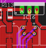
I see now I should have put a PIC option on the PCB. You are right, it would be a perfect interface block then. I might just do it anyway as there were a couple of minor errors on the board (notice the missing pins on the 90pin connector
Lucifix,
Thanks for the confirmation. I'm pretty sure I messed up my clock phase & data config somehow.
are you saying you talk to the SPI using a serial RS232 port? Can it be done?
Vladimir,
I see now I should have put a PIC option on the PCB. You are right, it would be a perfect interface block then. I might just do it anyway as there were a couple of minor errors on the board (notice the missing pins on the 90pin connector
Lucifix,
Thanks for the confirmation. I'm pretty sure I messed up my clock phase & data config somehow.
are you saying you talk to the SPI using a serial RS232 port? Can it be done?
Nice system you have there! What's the FPGA for?Thanks! In my system I already have an MCU (atmega16) that controls the display (4-bit mode), RC5 (remote control), user interface, CD drive state machine, DSA (CD drive serial control) and uses SPI for an analog volume control, FPGA init and now the S/PDIF receiver. It's starting to get crowded in there, so that's good news.
I've worked for few days with uC's hardware SPI (BTW I'm using a PIC18F uC) but I didn't find any option good enough to properly send/receive more than 16 bits of data in one "shot" (HW SPI CS signal was the main problem) so I've drop out the HW option and switch to the SW one.I'm pretty sure I messed up my clock phase & data config somehow.
For DMA you should keep the CS pin low to enable auto increment mode. I suppose, the HW serials will transfer 16/32 bits at most with CS pin controlled by internal state machines. So, there's no chance to make full DMA transfer in HW... only register-by-register R/W (unless you're working in FPGAs).are you saying you talk to the SPI using a serial RS232 port? Can it be done?
In my perspective, USART (RS-232) module is less flexible than SPI... maybe it's not an option at all as long as it have the data length of 8/9 bits. I wouldn't go that way. BTW are you using BlackFin to feed the SRC43x2 through SPI interface?
Best
Iain McNeill said:are you saying you talk to the SPI using a serial RS232 port? Can it be done?
Sounds to me like you'll have to program an MCU in the middle. Whenever I code up pretty much anything in embedded, first thing I do is put in RS232 for debug. Ant then the last thing I do in the project is to selectively compile out the RS232.
One thing to be aware of in DMA type accesses via RS232 is that the MCU may not be able to forward data fast enough. Particularly if you're sending ASCII on the RS232. In that case you'll need a wait loop on the PC side.
Let me know if you plan to use RS232 to talk to SPI. I have some C code that works on AVR atmega16.
Borge
In my application I'm using the Blackfin to communicate to the SRC over the SPI. The blackfin has DMA enabled SPI that can either disable CS after each byte or keep it low for the entire DMA dump. It's very flexible and I think this is my problem - I just haven't gotten the CPOL/CPHA configuration right.
I was just thinking of alternative applications for the board. A programmable, stand-alone SPDIF to I2S module would be handy.
As soon as I can clear some pay work out the way I'll take another look. A logic analyzer might help as well🙄 My trusty TEK465 ain't quite up to high speed digital debug.
Has anyone used any of these:
http://www.saleae.com/logic/
http://www.linkinstruments.com/mso19.htm
Well in the end I just slowed the baud rate down to 8KB/s and sampled the clock and data on my soundcard. Worked real nice and I saw that the SPI was working perfectly.
Turns out the CPM pin must be pulled low for SPI, not high.
DOH!!🙄
sings like a birdie now🙂
lets see what she can do
Turns out the CPM pin must be pulled low for SPI, not high.
DOH!!🙄
sings like a birdie now🙂
lets see what she can do
Well I'm impressed with my preliminary listening. I think I can hear an improvement. There seems to be more punch to the low end and overall more engaging sound - makes me want to put another track on.
Before I was listening to double converted audio - CD's played back by various means then re-digitized by my AD1836. Now, I'm digital all the way to crossover output. It's reassuring that I can hear one less conversion artifacts.
Took a while to get the SRC dialled in. I really wish the chip manufacturers gave you an interactive tool to config the registers. I had to roll my own:
SRC4392 configurator
Time to run some diagnostics😎
- Status
- Not open for further replies.
- Home
- Source & Line
- Digital Line Level
- S/PDIF to SPORT receiver PCB