You need to figure out which component is being affected by the heat. If you had fine gauge spray tube for the cooling gas, maybe you could aim it at one component at a time. Similarly you could probe with heat using a hot air soldering station with a small bore nozzle, or else with a solder iron set to a very low temperature. Just be careful not to burn or melt anything if you try using something that could get hot enough to cause damage.
Its also possible to use metal foil HVAC tape to make a heat shield for components you don't want to heat with hot air. https://www.homedepot.com/p/Nashua-...Weather-HVAC-Foil-Duct-Tape-1906077/100507541
Also, don't spray propane around anything actually hot! Get some real freeze spray and be safe.
Its also possible to use metal foil HVAC tape to make a heat shield for components you don't want to heat with hot air. https://www.homedepot.com/p/Nashua-...Weather-HVAC-Foil-Duct-Tape-1906077/100507541
Also, don't spray propane around anything actually hot! Get some real freeze spray and be safe.
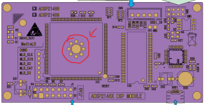
One possible point-of-failure is the exposed pad beneath the DSP chip. The connection may be poor or the soldering may have cracked which could lead to all sorts of problems even with light heating of the DSP chip. But as you don't have any noise with I2S heat may not be the real cause as I2S processing should heat the DSP just as SPDIF processing.
Too late Mark, I love propane!🙂 but seriously I will order one later.. and Im afraid its the dps chip, not 100% sure, it seems like blowing air anywhere on board helps.Also, don't spray propane around anything actually hot! Get some real freeze spray and be safe.
Tried make 'curtain' from cardboard, to see cooling which side helps more.. and its not obvious, both help and noise disappear for for some time..
Looks like small difference in temperature fix the problem.
Also maybe its like this cause 'cooling spread' easy to whole board cause of copper in ground/power planes?
You mean this pad?One possible point-of-failure is the exposed pad beneath the DSP chip. The connection may be poor or the soldering may have cracked which could lead to all sorts of problems even with light heating of the DSP chip. But as you don't have any noise with I2S heat may not be the real cause as I2S processing should heat the DSP just as SPDIF processing.

Or pad for spdif connection?
Should I try to reflow chip if other means fail?
Try to put heatsink on top of dsp?
Also will try to heat with i2s input just to be sure.
Didnt mention but I have dac, dsp in case on top of onkyo sr876 receiver, which is heating everything a bit.
If you think its the pad you might be able to squeeze the bottom of the board and top of the chip together a little. If there is just a hairline crack it might make a temporary connection. This assumes you have run out of other things to try.
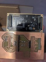
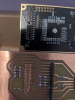
Also, what does the board look like on the bottom side under the middle of the DSP chip? Any via or other holes there?
Also, what does the board look like on the bottom side under the middle of the DSP chip? Any via or other holes there?
Yes, the circled pads. DSP chip has a square pad.You mean this pad?
It may be possible to just resolder the exposed pad from the bottom side if those round pads are vias. Reflowing the whole chip may be quite challenging.Should I try to reflow chip if other means fail?
So I have set up mixing spdif in + i2s in, inside dsp. Did heat it while source was spdif, got a lot of noise. I stop spdif, put play in raspberry pi and no noise.Also will try to heat with i2s input just to be sure.
Yes! I see the pad on bottom side.It may be possible to just resolder the exposed pad from the bottom side if those round pads are vias. Reflowing the whole chip may be quite challenging.
I have dsp board soldered to my board now.. i run out of 2.0mm raster sockets.. guess I will need to desolder. Will be hard to squeeze, but I will try to push down dsp chip. And yes there are some vias in neighbourhood of dsp.Also, what does the board look like on the bottom side under the middle of the DSP chip? Any via or other holes there?
Also will try to to locate spdif leg on dsp and push it with some plastic if anything change.
Found year old photos on my mobile


Doesnt help if there is change then for worse.. maybe pushed the chip even bit too hard, only thing that helps is spray.Also will try to to locate spdif leg on dsp and push it with some plastic if anything change.
So add flux, add more solder, and soldering iron at 350C?Looks kind of like a solder hole there in the middle of the octagon pad. Sometimes a hole is put there to hand solder the bottom pad of a chip. If that's what it is then it may be sufficient to re-melt the solder down in the hole. Use flux of course.
Have hot air also, but iron seems better for the job?
350C is probably around enough, depending. If not I would probably use a hotter iron. IME its usually best not to take too long to solder something, yet also good not use more heat than necessary to achieve a reasonable heating time. Its also good to clean the solder first by wiping off surface oxidation/contamination.
Last edited:
I was just reading the thread from the beginning and before the end of the first page I thought it’s freeze spray time! I see that someone came up with that idea! Freeze spray can find what is causing the issue when all else fails. If you don’t have any freeze spray you can turn a can off dust off spray upside down and it works like freeze spray.
Reworking that DSP chip with just a soldering iron could be challenging, but do-able I think. There are a few things that you may want to watch out for.
1. Solder. The board is most likely led-free assembled. You want to use 63/37 led-ed solder to mix in with and lower the melting temp. This is crucial for a successful rework without damaging the chip.
2. Flux paste. Apply plenty around the chip, and it will find its way in to the joint at temperature by capillary action. This is more important than using flux on the back side where you put the soldering tip. I mean plenty. There is no such thing as using too much flux.
3. A metronome. Or a metronome cellphone app. Beats at 60 or so per minute. Helps you time the heating.
4. Test for baseline timing. Cut a piece of perf board to size of a penny, and solder it to a larger piece of perf board, with redundant amount of solder. Let cool. With the metronome running, with the board standing on its side, heat from opposite side with an iron at 350c, use flux. Time the heating until the small piece starts to slide.
5. The amount of heating time needed in the actual rework can be much longer than the baseline time, due to led-free solder, inner layer planes and so on. Allow multiple try-and-test with incremental heating time.
6. Use the most massive iron tip you have.
So after 1 hour fight to desolder 26pin connector to disconnect dsp board from my board I gave up. Did try to put a lot of solder on pins.. did 'heat bridge from wire to all the pins.. tried hot air, and no success. Didnt want to heat it too much and risk damage, so I gave boards to local laptop repair to desolder it they also told they will melt pad.
Thanks for advices @nattawa, will definitely use if its not working after repair shop. Much appreciated 👍
Thanks for advices @nattawa, will definitely use if its not working after repair shop. Much appreciated 👍
I have good experience with mixing the existing high-temperature solder with low-temperature alloys. They are readily available from ebay. Rather nasty, need to be disposed of properly, but in combination with good solder flux work very good.
I melted pellets of Wood's metal from ebay in boiling water and poured the metal into plastic straws to make thin rods.
Also non-nasty low-temperature re-soldering alloys are readily available in good electronics stores.
I melted pellets of Wood's metal from ebay in boiling water and poured the metal into plastic straws to make thin rods.
Also non-nasty low-temperature re-soldering alloys are readily available in good electronics stores.
Little update, went to repair store today. Our deal was to desolder dsp board and melt ground pad. So they tell they resoldered the board 🤣 .. I tell them I wanted it desoldered, taken off... and strange talk start, why I need it desoldered, why melt the pad.. its just a pad.. crazy people. So I ended up with both connectors of dsp board soldered (was just when I gave it to them) and almost argue. They wanted like $5 for the job I never asked for🙂 ..ah well gonna have to visit another repair shop..
How are the boards soldered together? Ground plane to ground plane, is that why you can't get to the back of the DSP chip? If so, is there any space between the boards?
Depending on specifics, the most practical way to unsolder the boards might be to use a good quality tool like: https://www.google.com/search?q=hak...i57j0i512l7.3891j0j1&sourceid=chrome&ie=UTF-8
Not sure how many repair shops have something like that?
Or maybe there is a way to cut the pins between the boards to separate them, then remove the pins one by one? (The hard part is usually unsoldering them all at once.)
No, no just 2 pin headers (2 rows 13pins each row). Normally they go into sockets.. but I was out of sockets so soldered directly to other board -one connector all pins, from second connector just 2 pins to desolder easy later, so now I have both connectors completely soldered🙂. There is like 5mm space between boards.
There was no problem desoldering in repair shop.. just strange people, they didnt do what we agreed. So not going there again.
Found nice tricks on youtube:
but seems my soldering station dont have enough power.. too low temp(I did set to about 320C).. or lack of skills, anyway I didnt want to heat it too much.
I have this cheap soldering station https://botland.store/soldering-stations/7343-soldering-station-zhaoxin-936a-60w-5903351240444.html
Tomorrow will take boards to another repair shop.
There was no problem desoldering in repair shop.. just strange people, they didnt do what we agreed. So not going there again.
Found nice tricks on youtube:
I have this cheap soldering station https://botland.store/soldering-stations/7343-soldering-station-zhaoxin-936a-60w-5903351240444.html
Tomorrow will take boards to another repair shop.
Last edited:
Make sure they have a proper desoldering tool like the Hakko or similar. It should have a hollow heated nozzle, and vacuum suction through the hollow nozzle.
I now see why you didn't manage to de-solder the header..... YouTube could have presented a better idea than what's in that video.
To de-solder a long span of pins, you need a solid, stiff piece of straight copper wire, that lies right along the span of the pins. In your case, 1.2-1.5mm in diameter, 30mm in length will do. Rest the wire between the two rows of pins (the repair shop did you a good service by restoring the header to its fully seated position for that). Then pile the solder all over the wire and the pins, and rest the iron tip at the middle point, slanted so that a large surface area of the tip is in effective contact. With the copper wire acting as an extension of the iron tip, there is no need of moving the tip back and forth in frenzy. The excellent heat conductivity of copper wire spreads the heat quickly and evenly. You just rest the tip there, and wait patiently. It may take a lot longer than you would feel comfortable for the whole pile to start to melt, but there is really little concern of overheating at all. However, you probably do want to act without too much delay once the pile has become fully melted, as you don't want the header itself to get de-soldered from the DSP board.
Use plenty of flux.
Last edited:
The 2nd YouTube video above describes that exact technique. That video is much better than my lengthy, wordy post, but it somehow is a "video unavailable" on my phone.To de-solder a long span of pins, you need a solid, stiff piece of straight copper wire,
Yeah first video seems good if you desolder short pin header and you want to do it quick.
I was tryin second one but with wrong wire.. Thought I dont have thicker copper wire.. Or even where to get one? But I do have lots 1.5mm for electrical instalation. Wanted to try it again today, but now I realized I wont be able to pull out 1 headed in one step, since both soldered. Without solder I had to pull out quite evenly to remove board.
For repair shop 5min job if they have desoldering station.. Will see🙂
I was tryin second one but with wrong wire.. Thought I dont have thicker copper wire.. Or even where to get one? But I do have lots 1.5mm for electrical instalation. Wanted to try it again today, but now I realized I wont be able to pull out 1 headed in one step, since both soldered. Without solder I had to pull out quite evenly to remove board.
They would do better service If they did what what we agreed on 🙂 Not chenging job without informing customer. Just cause they think they know whats better for me..the repair shop did you a good service by restoring the header to its fully seated position for that
For repair shop 5min job if they have desoldering station.. Will see🙂
- Home
- Source & Line
- Digital Source
- S/PDIF input problem