Hi,
I am not a tube guy, so please assume I know little to nothing. I have been examining an amplifier kit constructed by a friend using the attached schematic.
The tubes are 11BM8s, which are pentode-triodes. The amplifier sounds fine.
However, I was surprised by the lack of a coupling capacitor between, for example, the plate of U1a and the control grid of U2a. Is this an error, or is this commonly done? I would think it could only work if the cathode voltage of U2a is quite elevated above ground and approached that of B+ so that the grid to cathode potential difference was minimal. There are no voltage measurements on the schematic of assistance to me.
Any insight would be appreciated. Just trying to learn something.
Thanks.
Attachments
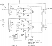
It's a very common circuit. The second stage is a split-load or 'concertina' phase inverter. Notice that its anode and cathode load resistors are equal in value. It's generally biased so the cathode is around 25~30% of B+ and the anode is 25~30% below B+. Direct coupling is convenient and even elegant as long as you're okay with the somewhat lower than ideal anode voltage on the input stage that often accrues. Split load inverters have no voltage gain, so the input stage will often be a pentode. Triodes configured for a lot of gain tend to increase input capacitance excessively due to miller effect. Is that enough to get you thinking?
Thanks for the wonderful explanation. Hope you don't mind if I keep exploring this a bit.
Let's say for discussion that B+ is 200 VDC. 25% below this for the anode would be 150 +VDC. And the cathode in your example would then be sitting at about +50 VDC, with a difference between cathode and anode of 100 VDC.
But with direct coupling, the control grid will be at 150 VDC....oops. I see that R2 biasing the plate on U1a is much greater (150K) than R4 biasing the plate on U2A (47K). Thus, the control grid of U2a will be quite a bit lower than the plate of the same tube. Got it. And the maximal current out of U2a will also be limited by the relatively low plate-cathode potential difference, at least compared to what the tube could do under maximal conditions, I suppose. (Part of my problem is that I can't seem to find characteristic curves for this tube, though I'm sure they are out there somewhere.)
Might you offer what I might expect for a grid-cathode potential difference on U2a as being typical in a circuit like this? Still near zero? (I know I can measure it, and will, but I just wondered what the general design is.)
Might you offer what I might expect for a grid-cathode potential difference on U2a as being typical in a circuit like this? Still near zero?
Yes. Still the typical value for Vg1k difference, a few volts only. The triode doesn't know what topology itself is in.
Part of my problem is that I can't seem to find characteristic curves for this tube, though I'm sure they are out there somewhere.
You can use the PCL82 datasheet.
An externally hosted image should be here but it was not working when we last tested it.
- Status
- Not open for further replies.