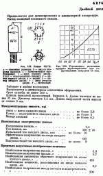
Can someone tell me what it says (translated to English) under the chart on the top right of this datasheet. It looks like current in milliamps is on the vertical axis, but I can't tell what is on the horizontal axis. Ua doesn't look like voltage. There's some writing below the chart that I'd like to know what it says.
Its over here, too.
http://klausmobile.narod.ru/td/data/_6h7b.GIF
http://www.klausmobile.narod.ru/td/list_e.htm#Signal diodes, detectors, converters etc
Its over here, too.
http://klausmobile.narod.ru/td/data/_6h7b.GIF
http://www.klausmobile.narod.ru/td/list_e.htm#Signal diodes, detectors, converters etc
Attachments
Last edited:
This type of problem has cropped up before. You could try scanning the document with OCR (optical character recognition software such as Abbyy that is often included with printers/scanners) and then copy and paste the text into google/bing translate.
Can someone tell me what it says (translated to English) under the chart on the top right of this datasheet. It looks like current in milliamps is on the vertical axis, but I can't tell what is on the horizontal axis. Ua doesn't look like voltage. There's some writing below the chart that I'd like to know what it says.
Its over here, too.
http://klausmobile.narod.ru/td/data/_6h7b.GIF
http://www.klausmobile.narod.ru/td/list_e.htm#Signal diodes, detectors, converters etc
It is plate voltage. Graph shows plate current vs. voltage around (+ and -) 0 volts.
This is a detector diode, so yes, it's Ua (U stands for "Ursache" in German, or cause) which indeed is plate ("Anod") voltage.
Right, and the anode voltage has been measured with a 40 K anode load resistor. (сопротивлений наргузки 40 ком)
Last edited:
I was wondering why there's current when the voltage is zero. Theoretically, when voltage is zero, current should be zero.
It's a detector diode designed for "miniature equipment".
The graph is (as already noted) current vs voltage.
The graph is labelled "the average initial anode characteristic", ie typical performance when new.
The graph is (as already noted) current vs voltage.
The graph is labelled "the average initial anode characteristic", ie typical performance when new.
Does Cyrillic work here?
усредненная - averaged
начальная - primary/initial
анодная - anodic
характеристика - characterization
при - at
сопротивлении - resistance
нагрузки - load
40 ком - 40 Kohm (assuming ком means Kohm)
(using Google Translation and Russian Keyboard OnLine with Spell Check (On-Screen Cyrillic Virtual Keyboard) for typing Cyrillic characters)
I was wondering why there's current when the voltage is zero. Theoretically, when voltage is zero, current should be zero.
Theoretically. However, in practice, electrons don't leave the cathode with zero velocity. Electrons that leave with an initial velocity will still hit the anode even when the Vpk is zero, or even slightly negative. It's similar (but not identical) to the reverse leakage current through a reverse biased SS diode.
If you look at the first graph on the third page here
http://www.wdv.com/Electronics/Radios/Hammarlund/pdf/6AL5.pdf
you can see that plate current is zero when voltage is zero (on the graph)
I'm wondering how the 6H7b would work in place of a 6AL5 in a ratio detector, for example. I have a couple 6H7b tubes and two 7 pin minature tube sockets which can be soldered to a 6H7b tube and used as a replacement for a 6AL5. Another idea I'm interested in trying is replacing the solid state diodes in a Pilot 100 stereo demodulator with vacuum tube diodes to see if the distortion is lower with tube diodes. Vacuum tube diodes are foward biased at a lower voltage compared to solid state diodes (about 0.3 volts for Ge and 0.6 volts for Si).
http://members.shaw.ca/pacifictv5/pilot100.jpg
Last edited:
The scan's a bit fuzzy but I think the vertical scale is in microamps [µA], not mA. In another datasheet (6Х2П, 6H2P) there's a similar graph as well as the one from 6AL5 (EAA91).If you look at the first graph on the third page here
http://www.wdv.com/Electronics/Radios/Hammarlund/pdf/6AL5.pdf
you can see that plate current is zero when voltage is zero (on the graph)
I fail to see how changing the 1N541 diodes for vacuum diodes will change the distortion. The ring demodulator diodes (hard to tell in the schematic, but it's a ring allright) act as switches. You may even introduce additional distortion because the vacuum diodes will have a higher forward voltage than the (I assume) germanium ones. But they're still used as switches... I take it you have an MPX generator and distortion analyzer to test your idea?
Last edited:
The scan's a bit fuzzy but I think the vertical scale is in microamps [µA], not mA. In another datasheet (6Х2П, 6H2P) there's a similar graph as well as the one from 6AL5 (EAA91).
I fail to see how changing the 1N541 diodes for vacuum diodes will change the distortion. The ring demodulator diodes (hard to tell in the schematic, but it's a ring allright) act as switches. You may even introduce additional distortion because the vacuum diodes will have a higher forward voltage than the (I assume) germanium ones. But they're still used as switches... I take it you have an MPX generator and distortion analyzer to test your idea?
Obviously, if I can hear the difference, then its worth doing. If there's no audible difference then its not worth doing. Look up crossover distortion.
This patent explains the time division multiplex system.
http://www.google.com/patents?id=Jb...urce=gbs_overview_r&cad=0#v=onepage&q&f=false
Last edited:
There's a mono/stereo switch on the Pilot 100 demodulator. When switched to stereo, there is more audible distortion compared to mono, especially with weak stations. Also, when comparing FM radios with solid state diodes (usually germanium) in the ratio detector and FM radios with 6AL5 diodes based ratio detectors, I noticed a smoother quality when a 6AL5 is used.
This is basically the Pilot 100 system.
http://www.google.com/patents?id=Jb...urce=gbs_overview_r&cad=0#v=onepage&q&f=false
This is basically the Pilot 100 system.
http://www.google.com/patents?id=Jb...urce=gbs_overview_r&cad=0#v=onepage&q&f=false
Last edited:
Here's a good explanation. Its so obvious and commonly known.
This is a similar (and simpler) arrangement to what they have in a Pilot 100 stereo demodulator.

Good webpage to look at -> AMZ Saturation Controls and Diode Clipping
from the webapage:
Crossover distortion
This is a similar (and simpler) arrangement to what they have in a Pilot 100 stereo demodulator.
Good webpage to look at -> AMZ Saturation Controls and Diode Clipping
from the webapage:
If we move the diode ground connection to a series position as in this example, we have an adjustable crossover distortion circuit. The signal level must exceed the forward threshold of the diodes in order for them to begin to conduct. This produces a "notch" in the output much like crossover distortion from early solid-state amplifiers.
Crossover distortion
An externally hosted image should be here but it was not working when we last tested it.
Last edited:
They have an example of a series diode circuit in this thread
Using LED's Instead of Diodes
http://i281.photobucket.com/albums/kk238/spliff-devine/gc/Silicon_ClippersClampers_002.png
Two of the circuits (lower 2) create crossover distortion.
The hardest thing to explain is the obvious.
Using LED's Instead of Diodes
http://i281.photobucket.com/albums/kk238/spliff-devine/gc/Silicon_ClippersClampers_002.png
Two of the circuits (lower 2) create crossover distortion.
The hardest thing to explain is the obvious.
Fair enough. But how can you be sure that these germanium diodes cause your perceived distortion? And what has crossover distortion to do with diodes that are used as on/off switches? Your examples have nothing whatsoever to do with the function of the ring demodulator in your Pilot 100 stereo decoder. And: how will you quantify whether your mod (replace four 1N541s with two 6AL5s or 6Х7Бs) is successful? In other words, do you have any test equipment?Obviously, if I can hear the difference, then it's worth doing. If there's no audible difference then it's not worth doing. Look up crossover distortion.
Finally, having years ago been involved in development of professional FM stereo demodulators, it should be noted that weak signal reception is nototiously cumbersome and frought with distortion due to multipath and defects in the IF strip, not the stereo decoder. You may want to compare with a known good receiver before attacking the poor diodes in your lovely little Pilot 100. Or even kludge together a (gasp!) IC based decoder (MC1310P or something more recent) to verify your setup.
Yes. It is similar to the tiny grid current which flows when a grid is slightly negative of the cathode - used for grid-leak bias. This effect has been used to generate electricity directly from heat.Miles Prower said:However, in practice, electrons don't leave the cathode with zero velocity. Electrons that leave with an initial velocity will still hit the anode even when the Vpk is zero, or even slightly negative. It's similar (but not identical) to the reverse leakage current through a reverse biased SS diode.
You can think of a vacuum diode as being like a semiconductor diode, except that the so-called 'threshold voltage' is not 0.6V but more like -0.4V, with wide sample variations. You can reduce this voltage by running the heater slightly cool.
This is a detector diode, so yes, it's Ua (U stands for "Ursache" in German, or cause) which indeed is plate ("Anod") voltage.
Hi,
the letter "U" is in german language the formula sign for voltage, probably derived from "Ursache" .
"Spannung verursacht Strom"
voltage causes current.
Ua = Vp
Uak= Vpk
- Status
- Not open for further replies.
- Home
- Amplifiers
- Tubes / Valves
- Russian to English Translation needed