Thanks guys.
@Zoran:
There will be a cathode follower at the output. It's planned.
In fact, I got a nice box in the metal waste dumpster, I have a switching power supply bought about $ 25 on Ali which delivers 6.3v and 300v and 50watts that I would like to test. About ten 6n8s tubes and various electronic components. It should be able to do it without too much expense right?
Thanks Zoran
But why damn it builders are giving such values ?
(And no distortion rate)
Look Rca and the soviet datasheet...
That is the mystery... I dont know copy-paste concept, somebody just said that sounds perfect - without any real argument? Mostly without any datasheet...🙁
I Order now 20k,24k,27k and 30k 3w resistors.
Uhhh... You are so fast?
Sorry I didn't wrote the power of resistors at the jpeg, especially Rload 🙂
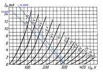
Lets see 13.5K @ 7mA = 13500ohms x 0.007A=94.5V drop @ Rload
Disipated power will be 94.5V x 0.007A = 0.6615W
This value can lead to wrong direction that 1W Rload will be fine BUT it is NOT like that. Use MINIMUM 4X calculated value! Rload or any other element should be just warm (DO NOT TOUCH HIGH VOLTAGE) and NOT hot...
So Your 3W are at the minimum power rating.
.
BUT with higher value of this from the example the DC voltage drop will be higher thus the dissipation will be higher. Please calculate before built.
.
And more important vith higher RLoad and same Vbattery You will shift opperating point to lower Vanode and other changes will include...
.
I think that these 2 x 27K/3W, (in parallel per 1 section) 6W total dissipation will be just slight warm in the preamp chases with long time operation?
Thanks guys.
@Zoran:
There will be a cathode follower at the output. It's planned.
In fact, I got a nice box in the metal waste dumpster, I have a switching power supply bought about $ 25 on Ali which delivers 6.3v and 300v and 50watts that I would like to test. About ten 6n8s tubes and various electronic components. It should be able to do it without too much expense right?
OK but that is just test circuit and with 300V of Vb power supply tube will work at the significant lower Anode voltage. Remember tube is the voltage device not current 🙂
.
I will draw You test circuit with that supply You already have to test
with that 300V supply You can move lto lower Va of about bit less than 200V (minus 6 V of bias if You use cathode R biasing)
try to stick with Ug to -6V line and about the 5 to 6 mA Ia.
Rk=1200ohms for 5mA to 860ohms for 7mA
Ck= 220uF for Rk=1200 and 470uF for 860ohm
cheers Marco
try to stick with Ug to -6V line and about the 5 to 6 mA Ia.
Rk=1200ohms for 5mA to 860ohms for 7mA
Ck= 220uF for Rk=1200 and 470uF for 860ohm
cheers Marco
Attachments
Hello Marco audio
In general, 6SN7 and equivalents work best with
7.5mA to 10mA Va (anode current)
-1.5V or more negative grid bias (or 1.5V or higher voltage at cathode if using self bias with cathode resistor)
300V DC plate supply (Ebb) or higher (up to about 450V)
ra (anode resistance) of 6SN7 under these conditions is usually about 8k ohms, so you want to use no less than 22k ohm Ra (anode load resistor). 27k, 30k, 33k all good, depending on Va, Ebb, Ia, etc.
If you have a +350V Ebb and you use 27k ohm Ra, you could use 510R for Rk and it should work well enough, giving you Va = 150V... (Just an example, not "the final word" on anything!)
--
Attachments
Hello.
Thanks Rongon for your comment.
I have resistors with less than 20 kOhms.
But the maximum for power supply is 300v.
Thanks Rongon for your comment.
I have resistors with less than 20 kOhms.
But the maximum for power supply is 300v.
Hello Marco audio
In general, 6SN7 and equivalents work best with
7.5mA to 10mA Va (anode current)
-1.5V or more negative grid bias (or 1.5V or higher voltage at cathode if using self bias with cathode resistor)
300V DC plate supply (Ebb) or higher (up to about 450V)
ra (anode resistance) of 6SN7 under these conditions is usually about 8k ohms, so you want to use no less than 22k ohm Ra (anode load resistor). 27k, 30k, 33k all good, depending on Va, Ebb, Ia, etc.
If you have a +350V Ebb and you use 27k ohm Ra, you could use 510R for Rk and it should work well enough, giving you Va = 150V... (Just an example, not "the final word" on anything!)
--
Sorry but this explanation is wrong and sort of as-is. Even for the test circuit with given limitations of Vb power supply of 300V
I dont want to start another flame really, sorry again...
Rule of thumb:
- For 'high fidelity' operation, you want the Ra (anode load) to be at least 2X the ra (triode internal resistance)
- Ra of 2X ra gives you maximum power from the triode anode into a load.
- Since 6SN7 ra = 8k, the minimum Ra is 16k ohms. That will give you the maximum power into a load from a 6SN7 (or 6N8S).
- You'll notice that with these low values of Ra, the loadline is quite vertical. That indicates less available voltage swing and generally higher distortion. But it does get you more power into the load.
- As Ra becomes greater than ra, voltage gain increases and (usually but not always) distortion decreases.
- Ra of 4X ra is usually chosen for line stage use, for lower THD.
- Ra of 4X ra for 6SN7 is about 30k to 33k.
- You'll notice that these higher values of Ra produce a loadline that is more horizontal. That indicates more available voltage swing and generally lower distortion. But it does mean less power into the load (lower current operation).
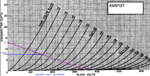
In this case, with Ebb of only 300V, a 33k Ra is probably going to give you low current operation. That might be fine, especially if this stage will be driving a cathode follower or other high impedance load. But if you want the stage to sink more current into a low impedance load, a smaller Ra will be necessary. That's OK too.
Load lines for Ebb = 300V and Ra = 20k, 24k, 27k and 30k. You can choose your own operating point, and you can figure out the value of Rk to achieve that operating point.
--
A couple of example operating points (I'm not saying they're 'perfect' or even 'desirable'. They're just examples.)
If you use Ra of 20k ohms:
Ebb = 300V
Ia = 7.5mA
Va = 150V
Vk = -3.6V (Rk = 470R)
If you use Ra of 30k ohms:
Ebb = 300V
Ia = 5mA
Va = 150V
Vk = -4.5V (Rk = 910R)
--
- For 'high fidelity' operation, you want the Ra (anode load) to be at least 2X the ra (triode internal resistance)
- Ra of 2X ra gives you maximum power from the triode anode into a load.
- Since 6SN7 ra = 8k, the minimum Ra is 16k ohms. That will give you the maximum power into a load from a 6SN7 (or 6N8S).
- You'll notice that with these low values of Ra, the loadline is quite vertical. That indicates less available voltage swing and generally higher distortion. But it does get you more power into the load.
- As Ra becomes greater than ra, voltage gain increases and (usually but not always) distortion decreases.
- Ra of 4X ra is usually chosen for line stage use, for lower THD.
- Ra of 4X ra for 6SN7 is about 30k to 33k.
- You'll notice that these higher values of Ra produce a loadline that is more horizontal. That indicates more available voltage swing and generally lower distortion. But it does mean less power into the load (lower current operation).
In this case, with Ebb of only 300V, a 33k Ra is probably going to give you low current operation. That might be fine, especially if this stage will be driving a cathode follower or other high impedance load. But if you want the stage to sink more current into a low impedance load, a smaller Ra will be necessary. That's OK too.
Load lines for Ebb = 300V and Ra = 20k, 24k, 27k and 30k. You can choose your own operating point, and you can figure out the value of Rk to achieve that operating point.
--
A couple of example operating points (I'm not saying they're 'perfect' or even 'desirable'. They're just examples.)
If you use Ra of 20k ohms:
Ebb = 300V
Ia = 7.5mA
Va = 150V
Vk = -3.6V (Rk = 470R)
If you use Ra of 30k ohms:
Ebb = 300V
Ia = 5mA
Va = 150V
Vk = -4.5V (Rk = 910R)
--
Attachments
Last edited:
Thanks Rongon for your comment.
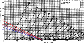
Ebb=300v,Ra=33k,Rk=560Ω,Vg~3v,Ia~5,4mA seems good to me...
(6n8s curves, soviet datasheet)
Regards
Ebb=300v,Ra=33k,Rk=560Ω,Vg~3v,Ia~5,4mA seems good to me...
(6n8s curves, soviet datasheet)
Regards
Last edited:
Hello diyers,
I'm studing now the cathode follower (DC coupled for my preamp).
1•)Is there someone abble to me explain why i can read on the web schematics who the voltage output is more than the input voltage ?!
Please.
I have learned than the cathode follower voltage gain is ever less than 1( A~μ/(μ+1) , for 6s7n~0,95).
Moreover some of these schematics seem "spiceed"...
2•)Rk:
Which value of Rk should i choose if the next stage input impédance is 47kΩ?
Does it matter ? (There is an 1 μf output capacitor in front of the 47kΩ)
A few value of Rk increase the current , Rk//47kΩ is lower than Rk.
In my point of view 33k should be enough.
Is it wrong ?
Regards.
Last edited:
Rule of thumb:
- For 'high fidelity' operation, you want the Ra (anode load) to be at least 2X the ra (triode internal resistance)
- Ra of 2X ra gives you maximum power from the triode anode into a load.
- Since 6SN7 ra = 8k, the minimum Ra is 16k ohms. That will give you the maximum power into a load from a 6SN7 (or 6N8S).
- You'll notice that with these low values of Ra, the loadline is quite vertical. That indicates less available voltage swing and generally higher distortion. But it does get you more power into the load.
- As Ra becomes greater than ra, voltage gain increases and (usually but not always) distortion decreases.
- Ra of 4X ra is usually chosen for line stage use, for lower THD.
- Ra of 4X ra for 6SN7 is about 30k to 33k.
- You'll notice that these higher values of Ra produce a loadline that is more horizontal. That indicates more available voltage swing and generally lower distortion. But it does mean less power into the load (lower current operation).
In this case, with Ebb of only 300V, a 33k Ra is probably going to give you low current operation. That might be fine, especially if this stage will be driving a cathode follower or other high impedance load. But if you want the stage to sink more current into a low impedance load, a smaller Ra will be necessary. That's OK too.
Load lines for Ebb = 300V and Ra = 20k, 24k, 27k and 30k. You can choose your own operating point, and you can figure out the value of Rk to achieve that operating point.
--
A couple of example operating points (I'm not saying they're 'perfect' or even 'desirable'. They're just examples.)
If you use Ra of 20k ohms:
Ebb = 300V
Ia = 7.5mA
Va = 150V
Vk = -3.6V (Rk = 470R)
If you use Ra of 30k ohms:
Ebb = 300V
Ia = 5mA
Va = 150V
Vk = -4.5V (Rk = 910R)
--
Hi this is not good "rule" in any way.
There is a major mistake about distortion. Does not matter what load line is until +I and -I signal the "same" as much as they can be. The difference in current half-periods are main parameter about distortion. Please take a look at the formula for the distortion at single ended anode-follower design.
Other thing about high RL is that the as higher RL is the AC current SMALLER and tube decreases driving capabilities.
The higher RL load lines are only try to virtually make tube linear...
The higher RL load lines "eating" the voltage from tube Anode making a tube low or medium low voltage device against high voltage device.
It is interesting how this unique "rule" damaged the audio tube design...
Inspired of exact datasheets for almost every tube with different parameters.
Last edited:
If You want almost "flat" load line tend to parallel Voltage axis, USE Inductor, choke (L) as load. With low drop DC voltage and inductance, capacitance, wire thickness and magnetic gap - matched to the tube parameters...
In this Marco's example he is determined with given values of power supply.
So that is OK to try - but that will be not the "true" sound of circuit and this tube.
.
The cathode follower is complete different circuit. Gain is +A<=1. +A means that circuit do not shift phase for 180deg. Phase in = Phase out.
The input signal is always a bit higher than output. BUT the output impedance is smaller than anode follower.
.
for 47K use minimum of 2 or 2.2uF capacitance. Calculate CR fiter with -3db@1.6Hz, for good phase shift and BW (that is -0.25Hz@20Hz) with standard formula.
.
For the cathode follower Dynamic capacitance is significantly smaller because of Gain=1, so You can use higher value of POT. Calculate first Cdynamic then find R with RC standard formula using -3db@131KHz cca.
.
Next stage input impedance is affecting value of load line. More ralistic load line is RL in parallel with next stage Rinput. So Use higher Rload value to match decease of Rload with Rin-next stage.
Last edited:
If You want almost "flat" load line tend to parallel Voltage axis, USE Inductor, choke (L) as load. With low drop DC voltage and inductance, capacitance, wire thickness and magnetic gap - matched to the tube parameters...
Hello Zoran.
Thanks but there it becomes too complicated for me.
A simple preamp with 3 stages is enough.
A dc cathode follower at the end and eventually a feedback loop linked to the first stage.
- Home
- Amplifiers
- Tubes / Valves
- Russian 6N8S/1578