Measure the voltage at pin 7 with a multimeter, set to DC. Clip the ground to the chassis and touch pin 7 with the + probe. Keep your left hand in your back pocket (assuming you're right handed). Only one (1) hand in the amp when the power is on.This may be the dumbest novice question ever, so go easy one me 😉, but how do I know the voltage shown here in this part of the schematic?
jeff

Ok, so no way to estimate/calculate it then?
I fiddled with the voltage from a bug zapper transformer once, thinking about building an electrostatic speaker. Scary voltages there.
That is rule #1. 🙂 I survived the last time I did this 30 years ago. One reason why I'm putting all of the voltages on the schematic, which the manufacturer put in the build directions but not on the schematic, is so I know what is where, although it's safest to assume that everything in there is dangerous (like a supposedly empty gun). ⚡⚡⚡⚡⚡Only one (1) hand in the amp when the power is on.
I fiddled with the voltage from a bug zapper transformer once, thinking about building an electrostatic speaker. Scary voltages there.
If you want to calculate the nominal voltage to complete your drawing, again Mr. Ohm is your friend (my own photographs).This may be the dumbest novice question ever, so go easy one me 😉, but how do I know the voltage shown here in this part of the schematic?
First you have to measure the DC resistance of the primary windings of your output transformer with an Ohm meter.
Of course before it is connected to anything.
You already know that the other numbers on the schematic imply a cathode current of (round numbers) 35mA.
From experience we can guess that screen current is 10%, say 3.5mA.
So plate current is 31.5mA, which causes the plate voltage to drop by V=0.0315*RP, when RP is the resistance of half a primary.
Knowing the primary's DC resistance will also be helpful to find out how well the pair of output tubes is matched.
Measuring the voltage drop across each half primary and Ohm's law tells you the actual plate current of each tube, which should not differ too much.
Attachments


Turn the amplifier off.
Disconnect the power cord, so you can not accidentally touch power mains.
Wait until B+ is totally discharged (you have to have a bleeder resistor across B+; safety first!).
Check your schematic, and find the bleeder resistor to be sure it is there.
If not, that is another posting to tell you how. Be sure to ask how to properly discharge the B+ before you add a bleeder resistor.
Carefully measure the B+ to be sure you have 0V B+.
Now, short the output transformer secondary, 0, 4, 8, 16.
Since the output transformer secondary is shorted, then Any DMM can read the DCR of the primary (many DMMs continually Auto-range if you do not short the secondary, the readings jump, so no correct answer for primary DCR).
First you have to measure the DC resistance of the primary windings of your output transformer with an Ohm meter.
That's easy. Will do.
Knowing the primary's DC resistance will also be helpful to find out how well the pair of output tubes is matched.
Measuring the voltage drop across each half primary and Ohm's law tells you the actual plate current of each tube, which should not differ too much.
THAT is excellent information! I had asked that question somewhere else I think, and it was on my "to do" list to figure that out. What would be an acceptable vs. unacceptable difference between the two, roughly?
Now, short the output transformer secondary, 0, 4, 8, 16.
Since the output transformer secondary is shorted, then Any DMM can read the DCR of the primary (many DMMs continually Auto-range if you do not short the secondary, the readings jump, so no correct answer for primary DCR).
Will do! Thanks. No need to worry about B+ (yet) as I have not started to build the kit, I have been making sure that I understand everything first as this is intended to be as much a learning experience as anything else after a 30 year absence from the hobby.
Check your schematic, and find the bleeder resistor to be sure it is there.
If not, that is another posting to tell you how.
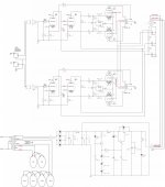
One interesting thing about the power supply board is that it has two LEDs that are supposed to indicate that voltage is there, I think. The schematic is attached. R7 (220k 2W) and LED D11 are there for safety, correct?
Attachments
Last edited:
After looking through the old kit directions from 4-5 years ago, and the new kit directions with its redesigned power supply, and the 6P14 tube specifications translated from Chinese, and some comments found online, I finally answered some more questions, in my mind at least. (Schematic with manufacturer recommended voltages in post above).
Apparently the Chinese 6P14 is not very tolerant of going very far outside of its voltage specifications like a 6P14P or an EL84. It's especially sensitive to anything over 300 volts on pin 9 (the screen, right?), which I suppose is why they have it regulated from the power supply. Many people online have said that the regulation "absolutely is not necessary." Well, apparently it is necessary for the 6P14. Maybe not so necessary for other tubes like 6P14P or EL84. Apparently anything even the slightest bit over 300 volts there will kill the Chinese 6P14 tube in a short period of time if not immediately. I suppose this is why the 91 volt "optional" zener diode is included with the kit, in case it is needed to get that down to 300 volts by replacing one of the 100 volt zener diodes with the 91 volt, correct?
Apparently the 6P14 also isn't too tolerant of too much over 300 volts on the plate. Using the comments from those of you above (thank you!) it appears as though that voltage ultimately will be between 325 and 345 volts. The manufacturer wants it to be closer to 325 volts for the 6P14, so I will have to see what happens when I finally build and test it. If it's sitting at 345V, then I don't expect the 6P14 tubes to last long at all, which is fine. I just want them to make sure the amplifier works. Apparently the EL84 can take that, albeit with a slightly shorter life per several online discussions, but not the 6P14.
Why the 6P14 is so sensitive to these voltages while other tubes are not is something I don't understand, but apparently it is so. Something in the construction of the tube is different I suppose. Perhaps something is in danger of arcing inside the tube? They don't seem to be too concerned about current as they never mention it. They are totally focused on the voltages.
Last edited:
The schematic you posted shows regulated supply for the output tube screens, max 300V, so I don't see what you are concerned about. You may need to optimise some settings at the end, but the design look good.
I use a CL90 Inrush current limiter on all the amps I have assembled, after the power switch on the primary side of the power transformer, and this can shave off a couple of volts and soften the power-on to the amplifier.
I use a CL90 Inrush current limiter on all the amps I have assembled, after the power switch on the primary side of the power transformer, and this can shave off a couple of volts and soften the power-on to the amplifier.
so I don't see what you are concerned about.
I'm not really any more given my latest post. What I needed to understand is why, especially the use of the 91V "optional" zener diode in the box to replace one of the 100V zener diodes, and the issues with the Chinese 6P14 not being tolerant of overvoltage like other tubes.
I'm not sure what this means in the instructions regarding tube life:
The high voltage regulated output voltage has a time-delay anti-impact function, and the voltage will be stable after 1 minute of power on.
I wonder what a time-delay anti-impact function is?
The behavior of pentodes is dictated by the screen supply, so ramping up the screen supply slowly ensures the tube is warmed up prior to seeing the max screen supply.
I think it is a 'nice to have' instead of being essential for this design, but shows attention to detail by the kit designer.
What are the transistors in the power supply? Just one value was on the schematic. Looks like a nice generic pentode supply.
I think it is a 'nice to have' instead of being essential for this design, but shows attention to detail by the kit designer.
What are the transistors in the power supply? Just one value was on the schematic. Looks like a nice generic pentode supply.
What are the transistors in the power supply?
They are there. This is all it says. I can barely read the writing on the two small ones, but they do say A94 and A44.
Q1 = A94
Q2 = A44
Q3 = 2SC3150
Since tubes were invented, there's been a long-term saying:
"Tubes are forgiving creatures" - which means they've got, and have been designed to have, a broad enough tolerence range in which they can operate.
Apparently, those chinese tubes don't follow traditional ways.
I'm certainly not a fan of delicate/touchy tube equipment.
"Tubes are forgiving creatures" - which means they've got, and have been designed to have, a broad enough tolerence range in which they can operate.
Apparently, those chinese tubes don't follow traditional ways.
I'm certainly not a fan of delicate/touchy tube equipment.
R2 is one bleeder
D5 and R3 are another bleeder
D11 and R7 are also a bleeder, but if the screen supply stops working, they do not bleed the earlier portions of the B+ capacitors.
After turning off the amplifier . . .
Always remember to check the various B+ capacitors for voltage before you get your hands in there. They take a medium amount of time to discharge, especially if your output tubes are missing, or go bad.
This is a helpful calculator. https://robrobinette.com/Tube_Bias_Calculator.htmHow do you calculate that, and would you leave it as-is?
Love your YouTube channel! Thanks!
And thanks 🙂
I don't know what a 330V zap feels like, and I don't want to find out. I'm hoping with all of the knowledge that I have gained here, I won't have to do much poking around or fiddling, just a little initial testing with the alligator clips that I have to keep my hands away. It's a pretty straight-forward build if I use the PCBs. With luck, I'll only have to test everything once.
About 35 years ago, somehow I tested a bug zapper transformer without killing myself. I remember having to build a high voltage probe to do it. I have no idea how. I was studying a DIY electrostatic speaker build at the time.
About 35 years ago, somehow I tested a bug zapper transformer without killing myself. I remember having to build a high voltage probe to do it. I have no idea how. I was studying a DIY electrostatic speaker build at the time.
This is a helpful calculator. https://robrobinette.com/Tube_Bias_Calculator.htm
I have been using that calculator all night long! According to it, the bias you mentioned is 87% with the included 150Ω resistors. According to the calculator, 160Ω from Mouser (in my shopping cart now) would take it down to 81.7%. I may do that. Someone in another thread suggested it. 87% seems very high to three different people now, including you.
And I watched another one of your videos this afternoon about how you wire your RCA jacks.
I think what they suggest is, that when the screen voltage comes out much higher than 300V, you can replace one or two of the 100V zeners with 91V type, to keep screen voltage below 300, which is desirable (more than plate v).
This is exactly the result. I swapped one of the three 100V zener diodes for a 91V, and the regulated voltage is now a perfect 297 volts.
I am hoping that increasing R1 from 100Ω to 200Ω, which is the simplest possible change, will slightly reduce the 407V (no load) power supply output, which is supposed to be 380V (no load), after it's all put together and tested.
Adding resistance won't change the voltage under no load conditions and honestly I never worry about what the no load voltages are other than making sure the caps are rated high enough to not explode when the amp is first powered up before the tubes start drawing power.
Right, I'll have to test it after assembly so there is a load. I have the 200Ω on order just in case. I suspect that I will need it because I am convinced this is a typical 110V transformer from China, not 115V as labeled, but haven't put to 200Ω in place yet because I can't test under load. The 275 volts out from the transformer is just over 300 volts, so I suspect I will need to use the 200Ω. Only one way to find out now ...
Last edited:
I wouldn't worry much over "no load" values.This is exactly the result. I swapped one of the three 100V zener diodes for a 91V, and the regulated voltage is now a perfect 297 volts.
I am hoping that increasing R1 from 100Ω to 200Ω, which is the simplest possible change, will slightly reduce the 407V (no load) power supply output, which is supposed to be 380V (no load), after it's all put together and tested.
Better to design with actual loaded voltages with all tubes present and cooking.
Trial and error usually results in satisfaction.
Actually, more than one way, at least theoretically. I downloaded and installed PSUDesigner from Duncan Amps and tested various values. What a great, free tool.I suspect that I will need it. Only one way to find out now ...
- Home
- Amplifiers
- Tubes / Valves
- Run power tubes at max voltage?