Something I came up with and plan to build shortly. I've started transferring my vinyls to digital and found out that I have a rather nasty arm-cartridge resonance at around 10Hz, easy to remove digitally but tedious, so I thought I'd see if I could put together something simple and effective with as few components as possible. I know, fix the problem at the source, but I foresee lots of trial and error and don't want to invest in a new arm or cartridge. Besides, resonance aside, it sounds fantastic as it is.
The delightfully simple (D. Self dixit) passive crossfeed is nice in that it only affects the anti-phase signal, but it provides only a gentle 6dB/oct slope that won't get you much attenuation where you need it unless you put the cutoff frequency way up. So I thought, how about cascading two of them to get a 12dB/oct slope? With the cutoff at around 63Hz (that would be now the -6dB point, since this is a Linkwitz-Riley, so the -3dB is around 100Hz, which I'm ok with for the anti-phase) you get ~32dB attenuation at 10Hz. To give you an idea, with a single stage you would have to put the -3dB point at around 400Hz to get the same attenuation at 10. So, not bad, but let's see if we can do better.
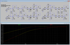
If now we add a conventional 3rd order high-pass (single opamp version of course) with a cutoff of ~14Hz, which gives -0.5dB at 20Hz (perfectly acceptable to me, ymmv) we get an extra 9dB or so attenuation at 10Hz for a total of 41dB, even better. That's the circuit on the left below.
Then, in the spirit of keeping component count as low as possible, I saw if I could get rid of the first crossfeed buffer, which works fine as long as you make the first cap at least 10 times larger than the second one (I went for 22 times for good measure) so the second stage doesn't load the first one too much. Next, the single-opamp Sallen Key is basically a 1st order followed by a 2nd order, so two resistors can go (yay!) if I re-purpose the input bias resistors of the crossfeed buffer for the 1st order stage putting a cap before them. Again, you don't want to load the second crossfeed stage too much, so a small cap and large resistor are in order (in the standard passive crossfeed circuit the resistor has to be large anyway for the same reason).
Finally I simply rearranged the whole thing with the 2nd order SK stage first to present an easy load to the RIAA stage (circuit on the right). As you can see the FR is pretty much the same (top trace is the in-phase signal, bottom trace the anti-phase). Due to the crossfeed component values, now that first opamp sees the load drop to about 1k for the anti-phase signal as you go up in frequency, but that should be no problem for an NE5532 or LM4562. As for DC offset at the output, it's likely that there will be a blocking cap already there before the next stage (don't remember, I haven't opened up the amp in a while) or I can always use e.g. an OPA2134.
Anyway, it's no Devinyliser but it's much simpler and I reckon it will do the job just fine. I have used component values of which I have a bunch so I'm sure I'll be able to find good matches. LTSpice file (using the included ideal opamp model) also attached for you guys to play with it. Stay tuned for the real thing.
The delightfully simple (D. Self dixit) passive crossfeed is nice in that it only affects the anti-phase signal, but it provides only a gentle 6dB/oct slope that won't get you much attenuation where you need it unless you put the cutoff frequency way up. So I thought, how about cascading two of them to get a 12dB/oct slope? With the cutoff at around 63Hz (that would be now the -6dB point, since this is a Linkwitz-Riley, so the -3dB is around 100Hz, which I'm ok with for the anti-phase) you get ~32dB attenuation at 10Hz. To give you an idea, with a single stage you would have to put the -3dB point at around 400Hz to get the same attenuation at 10. So, not bad, but let's see if we can do better.
If now we add a conventional 3rd order high-pass (single opamp version of course) with a cutoff of ~14Hz, which gives -0.5dB at 20Hz (perfectly acceptable to me, ymmv) we get an extra 9dB or so attenuation at 10Hz for a total of 41dB, even better. That's the circuit on the left below.
Then, in the spirit of keeping component count as low as possible, I saw if I could get rid of the first crossfeed buffer, which works fine as long as you make the first cap at least 10 times larger than the second one (I went for 22 times for good measure) so the second stage doesn't load the first one too much. Next, the single-opamp Sallen Key is basically a 1st order followed by a 2nd order, so two resistors can go (yay!) if I re-purpose the input bias resistors of the crossfeed buffer for the 1st order stage putting a cap before them. Again, you don't want to load the second crossfeed stage too much, so a small cap and large resistor are in order (in the standard passive crossfeed circuit the resistor has to be large anyway for the same reason).
Finally I simply rearranged the whole thing with the 2nd order SK stage first to present an easy load to the RIAA stage (circuit on the right). As you can see the FR is pretty much the same (top trace is the in-phase signal, bottom trace the anti-phase). Due to the crossfeed component values, now that first opamp sees the load drop to about 1k for the anti-phase signal as you go up in frequency, but that should be no problem for an NE5532 or LM4562. As for DC offset at the output, it's likely that there will be a blocking cap already there before the next stage (don't remember, I haven't opened up the amp in a while) or I can always use e.g. an OPA2134.
Anyway, it's no Devinyliser but it's much simpler and I reckon it will do the job just fine. I have used component values of which I have a bunch so I'm sure I'll be able to find good matches. LTSpice file (using the included ideal opamp model) also attached for you guys to play with it. Stay tuned for the real thing.
Attachments
Last edited:

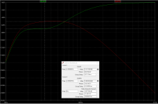
Something interesting I found out. I wanted to see if the filter behaves as expected when there's a signal only in one channel. Since below cutoff you're basically making the difference signal progressively tend to 0, you would expect a hard-panned signal to be progressively "monoized" at those frequencies. That's what happens, but with a twist, see the plot below (green channel with signal, red the other channel).
For some reason it's not just that half the signal appears on the other channel, it's actually louder there up until 60Hz or so, the maximum difference being about 2dB at ~33Hz. At first I thought, interaction between the two crossfeed stages? Putting back the buffer in between changes nothing, and the same goes for swapping back the crossfeed stage before the Sallen-Key. Then I simulated the filter with a plugin, so no circuit artifacts, and exactly the same thing happens. I guess it's just a, ahem, "feature" of the filter...
Of course the question is whether this is audible / bothersome, given the hard-to-locate frequencies where it's happening. I have a very good vinyl to check: Pat Metheny's Bright Size life, with Jaco's bass panned hard left. We'll see!
Attachments
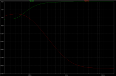
Very good point. I don't think a slight narrowing of the stereo would bother me much if it were uniform, but that line continues down at -6dB/oct so having it change so much from bass to midrange to treble may cause bad stereo artifacts. On the other hand, given the channel separation of typical cartridges, in fact that line will "merge" with the baseline 20-25dB curve pretty soon and level off (*), so maybe it won't be so bad... I don't know, maybe for archival purposes it'll be ok, I'll have to see. Many thanks for pointing it out!The channel separation is only 24 dB at 1 kHz, is that enough as far as you're concerned?
* (yup, this is what happens, see attached, assuming 25dB separation)
Attachments
Last edited:
You have to be careful with a second order cross-feed. Have a read of this A Second Order Elliptic Equalizer for Vinyl Mastering - Page 5 - Pro Audio Design Forum
Also note that some of the damage cannot be removed. The FM of the wanted signal will still be there.
As an aside calling it a 'rumble filter' has always seemed a bad idea. Most of the unwanted stuff is arm cartridge resonance, especially vertical below around 150Hz.
Also note that some of the damage cannot be removed. The FM of the wanted signal will still be there.
As an aside calling it a 'rumble filter' has always seemed a bad idea. Most of the unwanted stuff is arm cartridge resonance, especially vertical below around 150Hz.
This is true, and if baseband 10Hz is big enough to note, fm will be too.Also note that some of the damage cannot be removed. The FM of the wanted signal will still be there.
The better answer lies in tackling the problem at cause, generally via arm damping or by choosing a cart with more internal damping.
Still Ok to eliminate residual baseband sub-audio with filtering, but the fm is also well worth tidying up.
LD
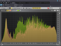
Thank you guys for your contributions, I'm definitely going to have to fix it at the source. Luckily I thought I'd try the plugin version first to see how well it worked. To my surprise I was only getting about 12dB reduction of the huge 10Hz peak. Why? Well, very simple: the vertical and horizontal components of the resonance are pretty much identical, see attached. That's the average spectrum (unfiltered) of Englishman in New York, red is the difference signal, green the sum. And yes, the FM is clearly noticeable at times (seems to come and go, for some reason).
In fact I have a Shure VST-V (V15-V by another name) that hopefully should improve things a lot with the damper. A pity because the Ortofon Nr. 2 (MC15 Super by another name) is in another league sound-wise.
Oh well, it was fun as an exercise, and it raises interesting questions about the assumption that this kind of resonance is mostly vertical. Maybe generally it is and I have an unusual problem with my specific setup (for info the turntable is a Rotel RP-855 with the stock arm), but at least it warrants some further research...
Attachments
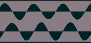
...and here's why. A snapshot of the 10Hz signal in all its glory just before the music starts: the L and R are almost exactly 90 degrees out of phase. What?😕the vertical and horizontal components of the resonance are pretty much identical
Attachments
Although we might talk about 'vertical' and 'lateral' headshell motion as though they are somehow separate, that is just an artificial construct we invent to make it easy to think about.
In reality, headshell motion is free in 2 dimensions, so the resonant system is a 2D one. That means all L-R vectors are possible, and any phase relationship between left and right channel outputs can and does happen and varies from moment to moment.
LD
In reality, headshell motion is free in 2 dimensions, so the resonant system is a 2D one. That means all L-R vectors are possible, and any phase relationship between left and right channel outputs can and does happen and varies from moment to moment.
LD
- Status
- Not open for further replies.
- Home
- Source & Line
- Analogue Source
- Rumble filter idea