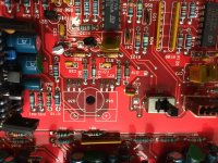
It looks like q36&q42 have been replaced, somewhat badly by the look of it, as well as the Zener diodes in the Op Amp power supply.
Those transistors should be TIP102& TIP107
Am I ok to briefly power up the board without the heat sink attached to check the Op amp Psu?
Those transistors should be TIP102& TIP107
Am I ok to briefly power up the board without the heat sink attached to check the Op amp Psu?
Attachments


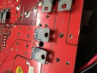
Power it up for a few seconds and check the temperature of all heatsink mounted components. Do this several more times with slightly longer times until you can see if anything is going to heat up.
They are likely OK. They are voltage regulators which will run warm (in some amps so hot that they will fail off of the heatsink).
Ok, that’s good to know. I measured the voltages from the Zeners and they are within a tenth of a volt of each other. The noise on the OPamp power rails measures around 10mv p-p and around 5mV rms.
That’s higher than I would like, I suppose it is within spec for the application but...
That’s higher than I would like, I suppose it is within spec for the application but...
Were you using a ground very near the op-amp for the black probe (scope probe ground)? When measuring critically, the reference is very important.
I wasn’t, I had grounded to a non bridging negative speaker terminal with an isolated scope. I’ll try again.
Some things you need to remember.
The PSRR of an an op-amp is 80dB+. People think 80dB is low but it's an incredible factor.
The frequency of the noise is likely well above audible.
The PSRR of an an op-amp is 80dB+. People think 80dB is low but it's an incredible factor.
The frequency of the noise is likely well above audible.
Yes, you’re right. If something is inaudible it doesn’t bother me, just a little surprised as Soundstream of this era were meant to be audiophile type in design and materials. It’s got 1% resistors for example.
On that note I pressed and prodded around the PS section after installing a patch in the damaged insulation, one of the 2200uF 35v rails caps seems looser than the other one and pressing hard on it sometimes causes a potential of -350mV to the amplifier casing, I’m going to pull it out and test it.
Could a bad rail cap result in the sort of unpleasant treble splashiness/distortion I’m hearing?
I don't know how a bad rail cap would affect the response. I'd expect it to allow a lot of noise on the output signal.
One cap was bad, it measured ok on the LC meter in terms of capacity but the leakage was quite high. The replaced both with some nichcon 105c low ESR jobs.
Now to test...
Now to test...
Did you repair the broken via? If it was partially displaced on the bottom, the connection to the top of the board was likely broken.
Did you repair the broken via? If it was partially displaced on the bottom, the connection to the top of the board was likely broken.
I don’t really know how to, I tried using a small piece of solid copper wire, soldered on to the top and ran through the hole. I then pushed the capacitor leg through and soldered it.
I’m not entirely happy with the repair as you can imagine.
Is there a proper way to do it?
There really isn't anything wrong with that as long as you had a long enough section soldered to the top so that it didn't come unsoldered when you soldered the bottom.
If both terminals on the inboard side of the caps goes to ground, you could additionally run a strip of solder braid to the other cap (insulated from the bottom traces, of course).
If both terminals on the inboard side of the caps goes to ground, you could additionally run a strip of solder braid to the other cap (insulated from the bottom traces, of course).
Ok, well the caps measure as being in the circuit they are supposed to be so I’ll call it a (messy) success.
The amp is back together and in the test rig.
When I first powered it up it made a horrendous farting noise through the left speaker.
I pulled the wire in panic and checked for bridges, shorts, etc.
I cautiously powered it up again and it’s fine, been playing music through it for half an hour now.
It sounds good but... perhaps a little sloppier in the treble than I would have.
Is there a cunning way to test for high frequency distortion?
If your scope can analyze frequency drive a pure sine wave into it and see if any harmonics pop up. That would only be for the simplest type of distortion.
How about this, you take two amplifiers (similar, solid state) and connect them to an A/B switch and let someone flip from one to the other and you see if you can hear the difference. Neither you or the helper should know which is which. Only after you pick the bad one 10 out of 10, then you determine which one sounded bad by looking at the way the switch was flipped when you heard what you didn't like.
It could all be your imagination... or not.
- Home
- General Interest
- Car Audio
- Rubicon 355 rising frequency response