I have used Martin King's "Sections" worksheets and Mathcad 8 to model a tapered TL using PE's RS180 in an mtm arrangement. Here is the frequency response. The blue line is a reference infinite baffle. The TL response is in red.
The TL sections are provided. Disregard sections of .001" length. They were part of the format I worked within and did not want to delete them.
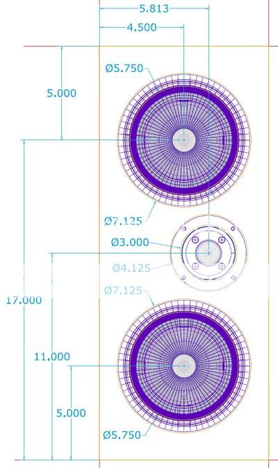
Tweeter height will be between 34-35" above the floor. It is loacted 10.37" below the top of the TL, at the beginning of the "open end".
The 10.8" section is the half-turn at the bottom of the cabinet.
The 4.46" section is the quarter-turn out the back.
TL length is 84.31"
The electro-mechanical values are included.
As this is my first serious attempt using these worksheets, I welcome all suggestions for improving the frequency response. I have found slightly better bass available at the expense of increased ripple. I think these are good dimensions to go with a cabinet for actual testing.
I will post a cabinet lay-out when I make a suitable one.
The TL sections are provided. Disregard sections of .001" length. They were part of the format I worked within and did not want to delete them.
Tweeter height will be between 34-35" above the floor. It is loacted 10.37" below the top of the TL, at the beginning of the "open end".
The 10.8" section is the half-turn at the bottom of the cabinet.
The 4.46" section is the quarter-turn out the back.
TL length is 84.31"
The electro-mechanical values are included.
As this is my first serious attempt using these worksheets, I welcome all suggestions for improving the frequency response. I have found slightly better bass available at the expense of increased ripple. I think these are good dimensions to go with a cabinet for actual testing.
I will post a cabinet lay-out when I make a suitable one.
The Frequency response:
An externally hosted image should be here but it was not working when we last tested it.
TL Sections:
An externally hosted image should be here but it was not working when we last tested it.
The electro mech's:
An externally hosted image should be here but it was not working when we last tested it.
newby to attachments
I'll try to adjust the attachment sizes WHEN I get my computer back. It crashed right after posting the above. I'm posting this from the computer shop.
I'll try to adjust the attachment sizes WHEN I get my computer back. It crashed right after posting the above. I'm posting this from the computer shop.


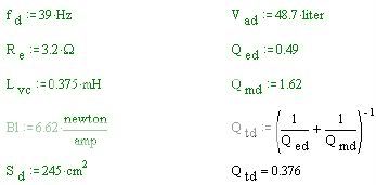
And here are the electro-mechanical attributes necessary to run a simulation. Remember, as an mtm both drivers are considered in the simulation. Look at the front baffle depiction. The virtual center used here is very close to the tweeter center.
Moderator's help
Thanks for your patience. Would a moderator delete posts 2,3,4, 6 and this one?
Thanks for your patience. Would a moderator delete posts 2,3,4, 6 and this one?
I've buitl an MTM TL in the past (using Martin's worksheets) whith about the same driver placement as yours.
It measured very close to simulations, and sounded quite good.
Porting to the back is good - you have not posted the port output, but i suppose there are high freq wiggles in them, and in the back they are less objectable.
Is the port close to the floor?
It measured very close to simulations, and sounded quite good.
Porting to the back is good - you have not posted the port output, but i suppose there are high freq wiggles in them, and in the back they are less objectable.
Is the port close to the floor?
Jorge,
The frequency response simulation in the post above does show ripple. The bass response and ripple are mutual trade-offs. Ripple can be reduced by increasing stuffing. Bass response is sensitive to changes in stuffing. So I strived for a good fit for both in the simulation. Since I haven't developed an ear for what the simulation shows, I think the next step is to build a prototype with some flexibility for listening and testing.
The port is at the top, in back.
I'm working on the cabinet diagram now. I didn't expect my computer to crash when it did or it would be posted by now. I feel extremely lucky to have such a good tech in the small town where I live. I used the opportunity to double my ram to 512K at the same time. I feel good about that.
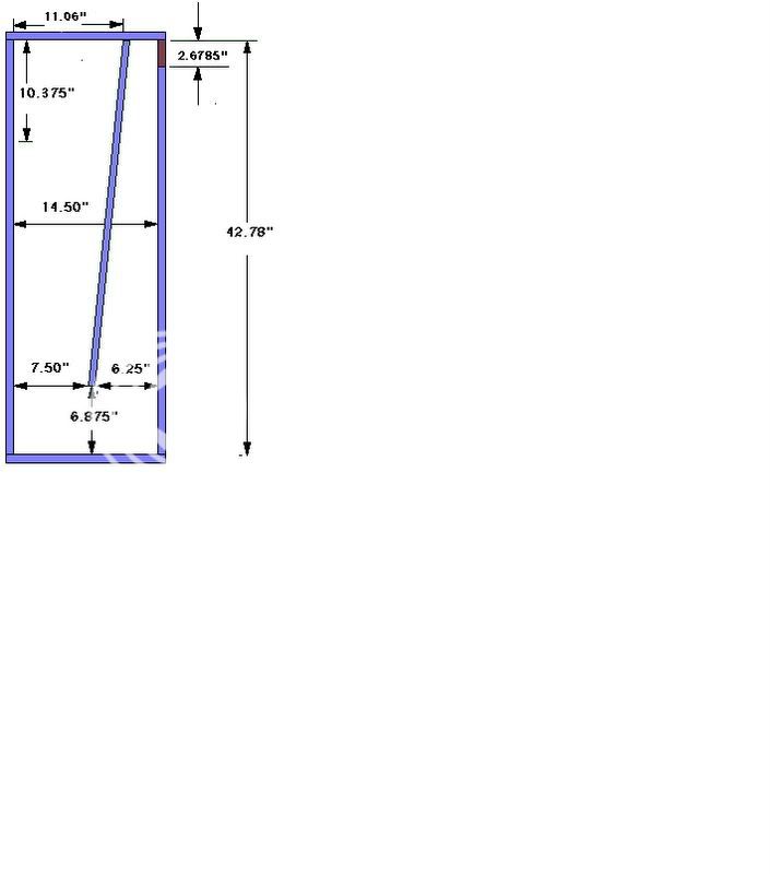
Here is a side view of the RS180 TL. The rear port is 2-11/16" high. (metric sure has it all over English measure). Corner baffles are planned, though beyond my current learning curve.
- Status
- Not open for further replies.
- Home
- Loudspeakers
- Multi-Way
- RS180 mtm TL