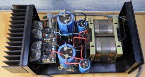
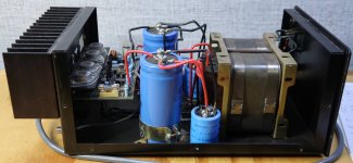
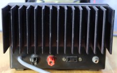
First turn P2 to minimal resistance (zero Ohm).Since there are no emitter resistors, how do I measure the bias ?
Swap the rail fuses for a pair of resistors ? (this is what Mr Tillbrook did on his aem6000)
Then connect 1R/2W resistors in place of F2/F3 fuses and connect the voltmeter across one of those 1R/2W resistors.
Turn on the amp and voltmeter shouldn't show any voltage.
Slowly turn the P2 until you read 300-400 mV on the voltmeter (that means 150-200mA through each MOSFET). Your pictures don't show the size of the heatsinks but that should be usual and safe value for those MOSFETs in class AB.
P1 sets the DC offset at the amp's output and it should be 0 V DC.
If it doesn't work like this, your amp is malfunctioning and needs repair.
If everything is OK and stable, turn the amp off, take 1R/2W resistors out, insert the fuses and you are ready to go.
Of course, feel free to change the caps that might get old and dry (after all, 1989 was 34 years ago)
And most of all, ignore everything cumbb says. Guy is a troll and is talking nonsense all the time, confusing the less experienced members. Lateral MOSFETs are among the best devices ever designed for audio - I use them since 1983 in numerous designs and yet have to find better ones (and I tested them all, including rare SITs).
Last edited:
"We lack the methods to trace the sound of components. I would start with power diodes. [...] first build a couple of single ended amplifiers with ONE power supply only. In this power supply insert different diodes, just like that in rail. Little by little. Just swap them. And always listen diligently and take notes diligently. After some experience add power transistors. Later the consideration, why the things sound different;-)"But are the TO-247's really better? The TO-3's are nice because they're hermetically sealed and avoid unnecessary ageing from water ingress through the moulded plastic. One advantage the TO-247's might have is the thermal gradient, but that may mean they need a slightly different circuit or different heat sinks for a fair comparison.
Many thanks Juma. Much appreciated.
I'm organising parts and instructions for the owner.
Trying to make it as easy/understandable as possible for him.
He's got the brains, so he wants to do the refurb himself as a fun project.
I'm getting him all new caps (including power supply), to-3 silpads, trimpots (never trust the old ones) hence the question about bias.
Offset is (almost) always universally simple.
And yes the heatsink is, small.
And yes, you see two power supply caps per rail. large one is 1,000uf, small parrallel one is 6,800uf. I've sourced some nice 16,000uf to replace these.
And bigger bridges to handle the increased start up surge.


Considering the amp is a mono-block, I guess I've seen worse heatsinks as well. If I was refurbishing these I guess I'd increase the bias until the heatsink get lukewarm even with lid on and leave it there.
Considering mosfets love bias to operate / sound decent, I'd rate these heatsinks as undersized.
Then again, to my untrained eye, the entire design is somewhat compromised.
I keep comparing it to the Tillbrook as I had one.
He did the research and made an amazing design.
Then again, to my untrained eye, the entire design is somewhat compromised.
I keep comparing it to the Tillbrook as I had one.
He did the research and made an amazing design.
Given a bias level of 100mA or more per pair of Mosfets, most lateral mosfet kit designs from the 1980s will sound quite good, though Dr. Tilbrook's original and very popular ETI series 5000/ ETI 477 pcbs would have become quite hot with around 40W total heat dissipated from a stereo pair at idle.
As it happened, it still wasn't biased high enough due to the shallow front panel heatsink casting and there were 12 x TO126 driver transistors inside, that also ran rather hot.
Most Latfet designs, including those fancy types worked up by Tilbrook here in Oz, wound up as somewhat underbiased to keep hardware costs down and avoid complaints about heat and the extra cost of dealing with it. It's a convenient strategy for bulletproof PA gear but falls short of hifi sound quality and disappointed many, like myself, who expected it but could find no explanation for the (then) general failure of DIY mosfet designs to deliver decent class AB audio.
Lots of images here: https://www.stereonet.com/forums/topic/255837-series-5000-mosfet-stereo-power-amplifier-upgrades/
The To247 is easier to mount just requiring one hole.
A TO3 uses 4 holes, 2 for mounting and 2 for B+E.
I use the pcb as a template for drilling TO3 heatsinks.
Drill one mounting hole then bolt pcb to heatsink.
Then drill second mounting hole and put a bolt through that.
The rest of the holes can drilled easily.
A TO3 uses 4 holes, 2 for mounting and 2 for B+E.
I use the pcb as a template for drilling TO3 heatsinks.
Drill one mounting hole then bolt pcb to heatsink.
Then drill second mounting hole and put a bolt through that.
The rest of the holes can drilled easily.
Important for TO-3 cases: use only one screw for electrical connection! The second screw without electrical connection.
The material of the screws has influence of the sound!
Use no solder lugs or shims.
Best: connect TO-3 case direct per wire, On top of it the shim and on top of it the nut. Use the screw hole further to the other two connecting little legs.
The material of the screws has influence of the sound!
Use no solder lugs or shims.
Best: connect TO-3 case direct per wire, On top of it the shim and on top of it the nut. Use the screw hole further to the other two connecting little legs.
- Home
- Amplifiers
- Solid State
- RS mosfet amplifier information wanted