
the above was meant to be a summary for this postI tried to get the mods to delete the post with the typos, but instead had the earlier one deleted ... not really my day.
In case that post cannot be resurrected, I will add a few quick summary points:
1. Transformer was established good. Conclusion was that plug was faulty. Also the schematic was out of date and the TX has no center tap.
2. put in a bridge rectifier GBPC2502W to replace the ESAB devices
3. All voltages are working fine - power board reconnected
the latest post and state of play is summarised here
Just for the record: The chassis ground is the center tap of the transformer and the negative of C907. Anyway, as it is working now, this doesn't matter any more.
C907 is most important for the bass performance of the amp. I would replace it with a new one a little larger, maybe 4.700uF. This will not hurt.
C517 and C617 should be replaced as well. Two 1.000uF/35V capacitors are cheap. You can use a higher voltage if 35 Volt are uncommon. Modern cap's are usually smaler, so it should be no problem to fit them. Electrolytics age! Some loose and some even gain in capacity, but distortion rises if they dry out. Maybe 7$ for all 3 of them and it will sound close to new. If both channels sound identical, there is little need to replace other capacitors. These 3 are the ones that worked the hardest.
There is a detailed instruction how to adjust the amplifier. If done correctly this should lead to best sound and reasonable idle loss. Take your time for doing this service.
Consider LED's as a replacement for the light bulbs which are hard to get. Fixing LED is easy with small drops of hot glue. If you change them all, just put a diode and a resistor in series with the 6.3 volt. You just have to find mini LED's with daylight color. Add a small capacitor if they flicker.
Hello, respectfully, I am not trying to argue, just trying to learn and hopefully explain.Just for the record: The chassis ground is the center tap of the transformer and the negative of C907
In the amp in front of me, there is no obvious center tap wire coming out of the TX, and going to ground.
The design in the schematic definitely does have a centertap, that goes to ground, and also forms the -ve of C907 as you describe. So are you basing your assertion on the diagram?
I am saying two things :
1/ the diagram has a different configuration for generating the DC, versus what I see on my amp, atleast so far as the diodes go. The diagram uses a single device, whereas the amp uses a pair of ESAB devices as mentioned above. So alteast in one crucual way, the amp and diagram differ.
2/ is it not possible to run a bridge rectifier configuration without a center tap? i agree a point in the bridge does form the -ve dc potential, and it might as well be grounded, and that ground then does have to be -ve of C907. And that is indeed the case here too. So, the chassis ground is the -ve of c907, but it need not be the center tap of the TX.
The TX is of course bolted to the chassis, so there is always a chance that the center tap is not visible, but still present.
But is a center tap absolutely necessary in this configuration ?
thank you.
Also, on your other points about the replacement caps and LED's , I fully agree, just looking online for replacements. I still need to figuere out the voltage issue I outlined in an earlier post.
Just had to keep the amp aside for a couple of weeks due to some urgent work issues.
thank you.
Just had to keep the amp aside for a couple of weeks due to some urgent work issues.
thank you.
Hi woodyp,
The schematic diagram and above picture shows the same device. A dual diode assembly (1/2 a bridge rectifier) with common cathode. Since these agree, I would be extremely cautious about changing things.
However, if for certain the winding does not have a centre tap going to ground (I am really doubtful), then yes. You can use a full wave bridge rectifier, positive to C907 positive, negative to C907 negative. This should already be connected to ground.
As I said before, it doesn't matter. I just wanted to correct your error, so you understand the cirqut right. Nothing with "I know better" as you may feel it to be, just to prevent you from mistakes that could result.
If you have a look at the service manual, page 6, paragraph 2. a. (2). it reads "secondary winding in the power transformer (center tap, black lead) is cut".
You have a black lead, so you have a center tap. I don't know why you can not accept the whole thing doesn't work without the center tap. Even as the manual says in plain words: "No center tap, no worky."
Also, it is a common mistake beginner do, to blame a mistake in a manual for not reading it right or not combining it with the physical amp receiver or what ever.
You can use a full bridge rectifier if you connect the two ends of the secondary to the AC inputs and the positive out to positive of C907.
The negative of the rectifier has to be left unused or cut off for safety. If the negative connects to chassis or ground, it will result in a defective fuse or transformer or worse.
You only use two of the four diodes inside the bridge and have a conveniant and robust part.
PS if you measure at positive/ negative of the bridge rectifier, you should measure more than 31 Volt.
Last edited:
Hi @anatech
The above picture is not posted by me, nor is it of my amp. It however does explain that the manufacturer changed designs. My layout doesn't look like it. Amp is closed up temporarily or i'd post it.
I have mentioned it in a prior post ... I already put in a Bridge rectifier GBPC2502W. The circuit had a pair of ESAB devices that together formed a Bridge rectifier, I have swapped the pair (one burnt) with the above single package. The schematic / service manual has a D902 which is a Full Wave rectifier , which necessarily needs a center tap. Bridge rectifier doesnt need a center tap as far as i know.
I am attaching a picture of the standalone board which I extracted out to do the modification. This is not represented in the picture posted by @huggygood above. The ESAB devices are removed and I had to find a spot for the GBPC2502W whose legs were too fat to go thru the holes.
I also had to put in a little connector (top right of the pic) for the secondary wires of the TX.

I will post more pics of internals when I next open up the amp in a few days.
The above picture is not posted by me, nor is it of my amp. It however does explain that the manufacturer changed designs. My layout doesn't look like it. Amp is closed up temporarily or i'd post it.
I have mentioned it in a prior post ... I already put in a Bridge rectifier GBPC2502W. The circuit had a pair of ESAB devices that together formed a Bridge rectifier, I have swapped the pair (one burnt) with the above single package. The schematic / service manual has a D902 which is a Full Wave rectifier , which necessarily needs a center tap. Bridge rectifier doesnt need a center tap as far as i know.
I am attaching a picture of the standalone board which I extracted out to do the modification. This is not represented in the picture posted by @huggygood above. The ESAB devices are removed and I had to find a spot for the GBPC2502W whose legs were too fat to go thru the holes.
I also had to put in a little connector (top right of the pic) for the secondary wires of the TX.
I will post more pics of internals when I next open up the amp in a few days.
Okay, that looks fine. It will work as it should, I was just very cautious about possible deviations from the way it was.
Having a manual disagree with what you have in front of you is reasonably common. Not normal, but not uncommon either.
Having a manual disagree with what you have in front of you is reasonably common. Not normal, but not uncommon either.
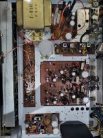
Here are some pictures as promised. Clearly looks a bit different from the one @huggygood posted above.
Maybe useful for some one in the future.
The cause of the odd voltage was just bad settings on the potentiometers, fixed when biasing.
Bulbs were replaced as well.
Sounds so sweet !
Pic 1 is top view
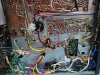
Pic 2 shows the power board which has the bridge rectifier and other voltages
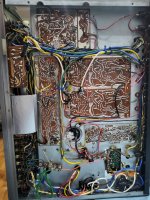
Pic 3 is the underside
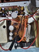
Pic 4 is closeup of output of power board (various DC) - the wire joins were put in for detaching and testing
Maybe useful for some one in the future.
The cause of the odd voltage was just bad settings on the potentiometers, fixed when biasing.
Bulbs were replaced as well.
Sounds so sweet !
Pic 1 is top view
Pic 2 shows the power board which has the bridge rectifier and other voltages
Pic 3 is the underside
Pic 4 is closeup of output of power board (various DC) - the wire joins were put in for detaching and testing
Attachments
- Home
- Amplifiers
- Solid State
- Rotel RX 400A Repair - Transformer problem?