Hi,
it is my first post here. Actually I'm a surgeon, but with high affinity to DIY audio 🙂
I had an OPS failure in a Rotel RSX-1067 AV reciever after an ouptut short. Output transistors, drivers and Q307 were blown, some resistors were disappeared. Fortunately I was able to obtain the transistors. The amp is about 14 years old and has probably over 4000h of service, and it ran pretty hot. So, since it's open, I'd like to recap the amp board, even though the electrolytic caps are still within their specs (they are marked "TK", 85° types). I'll use either Panasonic FR or Nichicon VZ.
I'd also like to change the ceramic disc caps to NP0 multi layers and the C308 (1uF electrolyte) to a foil type. Can this hurt? Is it worth changing C301 to an "audio grade" one, maybe bipoloar?
Greets from Germany
Attachments
Replacing electrolytics is a good idea. The ceramic caps are likely already NP0/C0G dielectric, so there will be no benefit in changing those.
C308 is not in the signal path, so no point to change it from an electrolytic. However you may want to consider a film cap e.g. Wima MKS2 for C301. C313 may benefit from being a bipolar capacitor, but there isn't much in it, as the DC across it will be tiny.
"Audio grade" electrolytics are of dubious value IMO... just go with good quality ones such as the parts you mention
Thank you! I think it's not worth changing c301 to a high quality foil - there is not much space there, even for a 4.7u... And there are about 5 electrolytes of the same type prior to it in the signal path (input buffer, pre, digital board etc. 🙂
Do standard old cheap disc caps use NP0/C0G dielectric?
Do standard old cheap disc caps use NP0/C0G dielectric?
They will have done in this case because otherwise there would be stability issues.. surprisingly it is possible to get "cheap looking disc caps" which are actually not crap 🙂
Well, first small problems 🙂
The power amp contains of two boards, one with four amplifier channels (FR (blown), FL, SR, SL) and one with three channels (Center, CBL, CBR). I've recapped both boards and replaced small parts in the blown channel.
Then, I decided to take two output transistors from the CBL channel, in order to use them in the FR Channel - the CB's are not in use here, and I wanted to have the output transistors in the front channels from one batch.
The new transistors (original Sanken, from DigiKey) I put in the CBL channel.
Then I tested the board with the NEW transistors, i.e the board which wasn't blown, using following setup: unregulated PSU +-20V, 22 Ohms resistors inline with power rails. No smoke so far 🙂 The square wave looks good on all three channels, but the quiescent current is different on the channel with new output transistors: I'm measuring 4 mV at the 0.22 Ohms emitter resistors in the original channels and 2.7 mV in the channel with new output transistors...
Since the channel will be unused, this might be no problem, but:
Why it is so?
Is my test setup valid (original PSU is about +-60V)?
Is quiscent current adjustable in this device? The board with the blown channel is not tested yet, maybe it will be fine, but who knows...Biasing is not mentioned in the service manual.
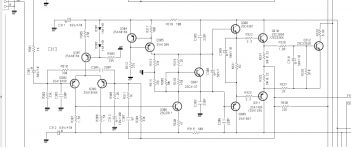
from the schematic, there is no trimpot for bias adjustment. One would have to alter the values of R306 and R316 to adjust the bias. Thats a pretty silly thing for Rotel to have done really.
Trim R306. R316 gets it in range, and swap out 306 with next value up/down to fine tune. If the outputs/drivers for a given production run are all from the same batches, the vbe' s will be very close and the same resistor can be used. It should be revisited if you put in new outputs.
OK, then I'll probably take also the original drivers from CBL and put them to "their" outputs to the front channel, the CBL will be populated with all new transistors. So maybe I'll only need to adjust bias for one channel.
With all new transistors, the bias in CBL channel dropped a bit deeper, but changing R306 to 5.1k fixed it, thanks for the advice. The "blown" FR channel runs with original transistors from CBL without adjustments 🙂
I hope there won't be any surprises with full rail voltage applied.
I hope there won't be any surprises with full rail voltage applied.
So, the device is assembled, up and running. The bias starts at 6 mV (about 30 mA) on all channels and goes up to 9.5 mv, when the amp warms up. Should be ok IMHO.
I recapped the PSU board too, and changed all the 1 uF electrolytes at outputs of 78xx's to wima mks2, they're located close to the regulators/heatsink and get pretty warm.
One 470 uF cap, sitting after the one way rectifier (45v for the display) gets pretty warm, about 45°C. I hope it will survive it, the original one did 🙂
- Status
- Not open for further replies.
- Home
- Amplifiers
- Solid State
- Rotel RSX1067 OPS failure - recap