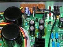
KC7 Adjustments
Hi!
IIRC you can adjust the KC7 by setting a voltage - with your multimeter, no scope needed. It's an approximation, but apparently is good enough. I'll need to dig out the details, but if you PM me, I can point you in Elso's direction if you need more info.
I need to check my KC7 in the CD80 in this respect - as it worked fine first time, I've not got round to it!
HTH
Jon
Yeah, I got this info from Kwak. Now if my Kwak Clock will just arrive... I ordered it over a week and a half ago and it shipped a week ago today... argh.
Hi,
I dug this out for the benefit of everyone. It came from Elso's instructions for the KC7.
"A ordinary probe gives kind of a distorted triangular wave shape.
If you have a scope with enough bandwith you will only see a squarewave if you use a homemade probe of 50 Ohm coax cable terminated at the scope with 50 Ohm from core to shield. Standard probes distort the waveform. Measure before the 0.01µF coupling cap!
Alternatively you can adjust the pot for +0.5 to +0.6V at pin 3 of the comparator. (best measured at the cap connected to the wiper of the pot)."
Cheers
Jon
Its a lot more clear in terms of instrument separation and imaging, but I am having a problem. The sound is really "flat" sounding, like the dynamic range just died. It sounds really "busy" and kind of muffled. Any suggestions?
Nothing that springs to mind.... I didn't come across this problem with mine. It worked first time and I haven't tweaked it yet. 🙂
Maybe some lurkers here might have some thoughts. You might try PMing Jean-Paul or one of the other guys who know a great deal about this sort of thing - I just built mine and fitted it.
Good luck!
Jon
Maybe some lurkers here might have some thoughts. You might try PMing Jean-Paul or one of the other guys who know a great deal about this sort of thing - I just built mine and fitted it.

Good luck!
Jon
Its sounding a lot better now. It just must have been a combination of burn-in and my ears (and brain) adjusting.
I suspect an implementation flaw in KC7, i.e. Q3(BC560) and TL431 for negative 5V output. The output voltage will not be -5V but a bit less than that. These 2 connected up does not regulate the voltage to -5V but works perfectly if its positive 5V. I've tried all sorts to get exactly -5V output on a breadboard and its NOT obtainable. Perhaps Elso's solution was best compromise.
Nevertheless the clock circuit still works.
Another possible solution is to implement what Sony has done in their older cd players..i.e. using Mitsubishi M5290 tracking regulator to obtain the required positive & negative rail voltage, henceforth scrapping the entire BC transistor/TL431 implementation altogether. Trouble is, I don't know whether this chip is still readily available or being produced. Perhaps there's some guru here who knows better.
Actually, I was looking for the schematic for the little regulator you built to tap off the big analog stage caps.
Super regulators
Hi,
I'm in the middle of constructing ALW Super regs for a load of uses. Might be of some use here.
Buy: http://www.at-view.co.uk/alwsr.htm
Manual: http://www.alw.audio.dsl.pipex.com/Manuals/ALWSR_rev2.9_iss009.pdf
Modify: http://www.pinkfishmedia.net/forum/showthread.php?t=21574
Cheers
Jon
Hi,
I'm in the middle of constructing ALW Super regs for a load of uses. Might be of some use here.
Buy: http://www.at-view.co.uk/alwsr.htm
Manual: http://www.alw.audio.dsl.pipex.com/Manuals/ALWSR_rev2.9_iss009.pdf
Modify: http://www.pinkfishmedia.net/forum/showthread.php?t=21574
Cheers
Jon
- Status
- Not open for further replies.
- Home
- Source & Line
- Digital Source
- Rotel RCD-02 Kwak-Clock upgrade
