Hi all,
I've been restoring a Rotel RA-314 recently as a bit of a hobby. It came to me with only one channel working, no VU backlights and the VU meters not working.
After a bit of chasing, I've got the amp back up and running (and sounding surprisingly good) with backlights, bar the VU meters, which have stumped me.
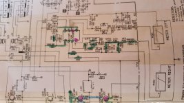
I've attached the Service Manual and a picture of what I've tested on one of the VU meter channels. Components highlighted in green are ok, purple denotes a problem.
The VU meters did not move at all - I've tested them and they move freely on diode test, so are not stuck. They maybe (although it may be my hopeful eyes) twitch a tiny bit once with load.
Originally I assumed that IC601 was at fault due to voltages on it's outputs, but having fitted a new working NJM4558DD in its place, I'm still getting the same readings.
IC601 reads/should be:
1= -0.06v / 0.87v
2= 0v / 0v
3= 0v / 0v
4 = -17.1v / -17.3v
5= 0v / 0v
6= 0v / 0v
7= -0.06v / 0.87v
8= 17.1v / 17.3v
The 10k pots (VR603 and 604) are fine, as are the diodes/res in the right meters (M002) path - I've not tested the caps in the line as they're ceramic and don't normally go (maybe I should?).
Any help would be appreciated, thanks in advance for any help given 🙂
I've been restoring a Rotel RA-314 recently as a bit of a hobby. It came to me with only one channel working, no VU backlights and the VU meters not working.
After a bit of chasing, I've got the amp back up and running (and sounding surprisingly good) with backlights, bar the VU meters, which have stumped me.
I've attached the Service Manual and a picture of what I've tested on one of the VU meter channels. Components highlighted in green are ok, purple denotes a problem.
The VU meters did not move at all - I've tested them and they move freely on diode test, so are not stuck. They maybe (although it may be my hopeful eyes) twitch a tiny bit once with load.
Originally I assumed that IC601 was at fault due to voltages on it's outputs, but having fitted a new working NJM4558DD in its place, I'm still getting the same readings.
IC601 reads/should be:
1= -0.06v / 0.87v
2= 0v / 0v
3= 0v / 0v
4 = -17.1v / -17.3v
5= 0v / 0v
6= 0v / 0v
7= -0.06v / 0.87v
8= 17.1v / 17.3v
The 10k pots (VR603 and 604) are fine, as are the diodes/res in the right meters (M002) path - I've not tested the caps in the line as they're ceramic and don't normally go (maybe I should?).
Any help would be appreciated, thanks in advance for any help given 🙂
Attachments
Hi Jon,
Thanks for the reply.
I've not got a scope (I did have but it went pop sadly), but 1 and 7 on IC601 fluctuate on voltage under load, although never really above c. 0.01v.
The VU's have a res of about 0.6k between + and - There's no shorts to ground from the +.
Thanks again for reply.
Thanks for the reply.
I've not got a scope (I did have but it went pop sadly), but 1 and 7 on IC601 fluctuate on voltage under load, although never really above c. 0.01v.
The VU's have a res of about 0.6k between + and - There's no shorts to ground from the +.
Thanks again for reply.
A scope would be a big help. I wouldn't worry to much over the voltage discrepancy because the opamp is configured with those rectifiers within the feedback loop and so things could be a little unpredictable depending on diode leakage currents.
Are you sure you have enough signal present. You could set the main output (no speakers attached) to give say 2.8 volts AC as read on a DVM and with a 400Hz or thereabouts test tone and then take things from there and see what the meters show (or don't).
Are you sure you have enough signal present. You could set the main output (no speakers attached) to give say 2.8 volts AC as read on a DVM and with a 400Hz or thereabouts test tone and then take things from there and see what the meters show (or don't).
Hi Mooly,
Thanks for the reply. Yeah, my scope died a few months ago, so currently looking for a new one.
So, I've had a play with Vr601 and 602 (the bias adjust) and they do very little to shift the main output (although they seem to be mechanically working ok). Can't shift the output any further than -25mv. Cranking VR603/604 up under load makes the VU needles shift a teensie bit, so I think you may well be right in that there's not enough signal present.
Audio plays fine (well it would at those levels), I've already checked out on the right and left channels Q604, 606, 608, 610, 612 (which was shot), 614 and 616 (and equiv).
Thanks again!
For testing purposes I would just set those presets to give max signal (so wiper turned to the coupling cap end of its travel).
It is definitely worth doing some basic tests of levels, even just using a meter.
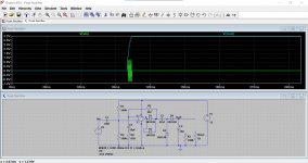
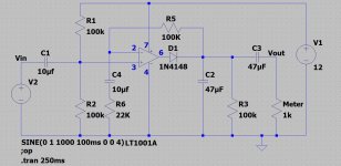
I had a peak rectifier circuit already set up as a simulation and so I've just plugged your values into. The DC voltage across C628 (so C2 in my diagram) comes out at over 3 volts DC for a 1 volt peak ( so just 0.7 volts rms at the speaker terminals).
My input signal was just a toneburst and with nothing to load the cap the voltage is held. A constant tone would give constant voltage. in your actual circuit.
It is definitely worth doing some basic tests of levels, even just using a meter.
I had a peak rectifier circuit already set up as a simulation and so I've just plugged your values into. The DC voltage across C628 (so C2 in my diagram) comes out at over 3 volts DC for a 1 volt peak ( so just 0.7 volts rms at the speaker terminals).
My input signal was just a toneburst and with nothing to load the cap the voltage is held. A constant tone would give constant voltage. in your actual circuit.
Attachments
Thanks again for the reply.
I've had a quick look - loaded a constant 1khz signal with both the bias and VU meter pots to max, volume up.
At the speaker terminals its 31mv max - won't go any higher. C628 reads a constant 14.1v, drops off as soon as the signal drops.
I reckon I'm going to have to replace my scope - my old one was originally my fathers, any recommendations for a new one that won't break the bank?
Thanks again 🙂
You say in post #1 it is all playing OK and sounding good and so you must be able to get more than 31mv at the terminals. Remember the signal is an AC voltage and 2.83 volts rms would equal 1 watt into 8 ohm.
31 mv sounds more like a DC offset tbh. If it is playing normally then you must be able to get the full range of AC voltage at the speaker terminals. 20 volts AC would be equal to 50 watts rms into 8 ohms. If you use a frequency in the 50 to 400Hz range then it guaranteed to be within the DVM's frequency range.
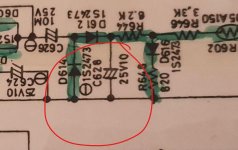
If C628 (see attached) has 14 volts on it then the meter should be pegged hard over... because that is the driving voltage to the meter movement via those remaining resistors and thermistor.
Just trace that voltage (the 14 volts) to the meter and see where it all falls apart 🙂
D616 and its series resistor are a clamp and will limit the voltage to around +2 volts DC as a maximum at that point.
Are all the grounds OK? No floating grounds at the meter or around those rectifier parts.
Its a long time since I bought a new scope. I'd probably say a good analogue type is still your best bet (loads on the usual kind of sites for that). Dual trace and 30Mhz as a minimum.
New digital scopes are very popular but you need to pay big money to even approach the resolution of even a modest analogue one as for example when looking at complex high frequency signals.
31 mv sounds more like a DC offset tbh. If it is playing normally then you must be able to get the full range of AC voltage at the speaker terminals. 20 volts AC would be equal to 50 watts rms into 8 ohms. If you use a frequency in the 50 to 400Hz range then it guaranteed to be within the DVM's frequency range.
If C628 (see attached) has 14 volts on it then the meter should be pegged hard over... because that is the driving voltage to the meter movement via those remaining resistors and thermistor.
Just trace that voltage (the 14 volts) to the meter and see where it all falls apart 🙂
D616 and its series resistor are a clamp and will limit the voltage to around +2 volts DC as a maximum at that point.
Are all the grounds OK? No floating grounds at the meter or around those rectifier parts.
Its a long time since I bought a new scope. I'd probably say a good analogue type is still your best bet (loads on the usual kind of sites for that). Dual trace and 30Mhz as a minimum.
New digital scopes are very popular but you need to pay big money to even approach the resolution of even a modest analogue one as for example when looking at complex high frequency signals.
Attachments
Hi,
Thanks (yet again) for the replies - really appreciated. Sorry for the late reply, been busy the last couple of days digging up dead Saxons.
@jaycee - the meters are functioning - checked out and they both move under diode test on the DVM freely.
@Mooly - yep, I'm an idiot - I was testing DC offset at the terminals......
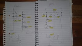
I've taken readings over the diodes, caps and res in the rec areas for both left and right VU's (see attached badly drawn schematic), again with a 1khz constant signal.
The channels are uneven, (with a 10v diff between left and right over C627/628), running after the clamps (R = D616, R648 : L = D615, R647) the right chucks 1.2v through R646 and the left 1.93v. When the voltage runs through both thermistors TR601 and TR602 it drops down to R=0.16v and L=0.25v. Not sure if it's the thermistors or not - I tested the right one out of circuit the other day and it seemed to operate ok (think they're NTC).
The right VU needle shifted during testing to a mid point, moves ever so slightly but still no dice. Looked for floating grounds, couldn't find one.
Thanks again for all the advice - much appreciated.
Thanks (yet again) for the replies - really appreciated. Sorry for the late reply, been busy the last couple of days digging up dead Saxons.
@jaycee - the meters are functioning - checked out and they both move under diode test on the DVM freely.
@Mooly - yep, I'm an idiot - I was testing DC offset at the terminals......
I've taken readings over the diodes, caps and res in the rec areas for both left and right VU's (see attached badly drawn schematic), again with a 1khz constant signal.
The channels are uneven, (with a 10v diff between left and right over C627/628), running after the clamps (R = D616, R648 : L = D615, R647) the right chucks 1.2v through R646 and the left 1.93v. When the voltage runs through both thermistors TR601 and TR602 it drops down to R=0.16v and L=0.25v. Not sure if it's the thermistors or not - I tested the right one out of circuit the other day and it seemed to operate ok (think they're NTC).
The right VU needle shifted during testing to a mid point, moves ever so slightly but still no dice. Looked for floating grounds, couldn't find one.
Thanks again for all the advice - much appreciated.
Attachments
...I had a peak rectifier circuit already set up as a simulation....
You have your D1 D2 in the wrong leg of the loops. In the 2.2k leg they pre-distort the signal a diode-drop high, neatly offsetting (about) the drops in the diodes to the meter.
Won't make a functional difference but will somewhat offset your results.
Attachments
Last edited:
Is the ground connection missing ?
C628 and 627 are grounded or should be and so you should not have 14v on each side of the cap. The ground is at the meter on the diagram.
C628 and 627 are grounded or should be and so you should not have 14v on each side of the cap. The ground is at the meter on the diagram.
You have your D1 D2 in the wrong leg of the loops.
Thanks 🙂
That's what happens when you take a hatchet to an already existing sim.
Attachments
Is the ground connection missing ?
C628 and 627 are grounded or should be and so you should not have 14v on each side of the cap. The ground is at the meter on the diagram.
Ah, that's my crappy annotation - apologies. 14v not on both sides of the caps. 14v across the cap, 0v on the ground.
Ground continuity is fine across the requesit points, all to chassis.
Its stumped me to be honest - it can't be the meters as they shift happily under the diode test on the DM.
Looking at the voltages across the thermistors and at the meters themselves, is 0.2v enough to shift the needles?
*edit - if I flick through inputs, both needles under 1khz move 1mm up when flicking back onto the aux with the signal.
Thanks again!
Last edited:
No problem 🙂
So 14 volts DC across the cap and with a 600 ohm meter resistance should see around 1 volt across the meter. That's just ohms law and the diode clamp volt drop taken to be about 500 to 600 mv at low current.
The thermistor value is an unknown and the above assumes it is really low resistance.
200mv DC across the meter should deflect it it pretty much fully I would have thought.
Your real test is to do as I mentioned earlier and set the AC voltage at the speaker terminals to 2.83 volts with the test tone.
The meter should read 1 watt at that voltage level. If it doesn't then we need to look at what voltages you actually have present under those conditions. We could also test a meter out of circuit with a battery and a pot to see what its full scale deflection voltage is.
And just thinking about it... your 600 ohm meter movement probably isn't that sensitive by definition of that 600 ohms and so would be more like perhaps 0.3 or 0.5 milliamps to deflect fully which would need perhaps 300mv to fully deflect.
I've had problems with precision rectifier circuits like these before. The fault? Well, the usual one is wherever you find small electrolytic caps associated with timing or gain circuits. Typically, little electrolytic caps dry out and fail first and this also is a common fault with speaker protection relay circuits.
I wouldn't bet on it but lookit all those 10uF electrolytics in the meter circuits! That's trouble, especially in if in a warm part of the amp. and it's where I'd look first and buy some spares and fit them regardless of their condition. 'may as well replace the 2 x 47uF while you're in there.
I wouldn't bet on it but lookit all those 10uF electrolytics in the meter circuits! That's trouble, especially in if in a warm part of the amp. and it's where I'd look first and buy some spares and fit them regardless of their condition. 'may as well replace the 2 x 47uF while you're in there.
- Home
- Amplifiers
- Solid State
- Rotel RA-314 - VU Meters Not Working