Hi people, I've read a few posts regarding this CD player 971. Uses PCM chips. My question is in regards to a mod I seen online and I never seen anything like it. Simple enough as you can see from the pics its.
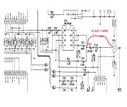
Its a 100nf + 100r resistor from input of output cap to output terminal. From website: "And also bypass the DC blocking Caps (C717 and C718) with a 100n PP (i.e. EVOX-RIFA) and a good quality 100 Ohm resistor directly to the output plug. Never connect two caps directly in parallel because of the current resonance problem."
My question is why? I always bypass caps directly, why is it connected this way and why the 100r resistor? What significance will this have on the frequency?
Any info would be appreciated. Thanks
Attachments
The resistor damps the RLC circuit formed (where L is the larger capacitor's inductance, and C is the smaller capacitor).
https://www.intmath.com/differential-equations/8-2nd-order-de-damping-rlc.php
https://www.intmath.com/differential-equations/8-2nd-order-de-damping-rlc.php
Thanks but what does that mean in Layman terms? Why 100nf? Is a 1uf film cap better or lower better?
Does the "mod" improve the sound? What is it actually doing?
When it comes to complex circuit designs I'm completetly lost.
Does the "mod" improve the sound? What is it actually doing?
When it comes to complex circuit designs I'm completetly lost.
It's a matter of controlling the RLC resonance caused by the larger capacitor's inductance.
Although, some wound capacitors have low inductance because they have extended foil ends.
The actual value of the smaller capacitor is somewhat arbitrary, if the calculated resistor value is acceptable.
The smaller C should have much lower inductance than the large capacitor for this to work properly.
The formula for critical damping, which is: R = 2 x sqrt(L/C) ---- where L = inductance of large C, and C = smaller C,
allows you to calculate R, if given the smaller C and the inductance of the larger C.
Or, given R and the larger capacitor's inductance, you can calculate the value of the smaller C.

I was hoping for a much more simple answer. I'm going to try the circuit with a 2.2uf film cap I have lying around and 100r resistor
I would leave that alone, the consequences for getting it wrong can be catastrophic. If that output cap turns into an antenna, your amp isn’t going to play when the wrong frequencies cause oscillation.
Look up R C filters and plug in some numbers to see how you’re changing things.
You should always have a very good understanding of how deep the water is before jumping off that cliff.
Look up R C filters and plug in some numbers to see how you’re changing things.
You should always have a very good understanding of how deep the water is before jumping off that cliff.
- Home
- Source & Line
- Digital Source
- Rotel opamp output cap?