I'm hoping to build a rotary speaker cabinet from two units I have reclaimed from inside a couple of old yamaha organs. What I would like is connect both to the output of my 15watt laney cub have the speed controller as a foot switch or rocker pedal. Both units need 110V AC.
I don't know anything about electronics except how to solder so please forgive the noob questions.
Here is a video of someone who has made a similar cabinet.
Yamaha 2 speed Rotary Speaker unit - YouTube
info gleamed from youtube video:
All you need to know is that the Green and Orange wires are for the 110vac to power the unit, the Violet wire is common ground but you don't need to use it so just cut it off. The Red, White & Yellow wires are exactly what he describes in his video and are used to select the rotation speed - Red wire is common. If you like, you can ignore the White wire and just hook up the Red & Yellow to a 500K linear variable resistor and change the speed of the rotation to suit.
The speakers are 8ohms each
Problems I need help with:
• What power supply will I need to power both units from one supply?
• Will I need a stereo pot (variable resistor) to control the speed on both units at the same time.
• When I hooked up one speaker to my amp (15watt) the output level was a lot lower then the normal speaker (also 8 ohms). Any ideas why this might be?
Thanks for your help
I'm hoping to build a rotary speaker cabinet from two units I have reclaimed from inside a couple of old yamaha organs. What I would like is connect both to the output of my 15watt laney cub have the speed controller as a foot switch or rocker pedal. Both units need 110V AC.
I don't know anything about electronics except how to solder so please forgive the noob questions.
Here is a video of someone who has made a similar cabinet.
Yamaha 2 speed Rotary Speaker unit - YouTube
info gleamed from youtube video:
All you need to know is that the Green and Orange wires are for the 110vac to power the unit, the Violet wire is common ground but you don't need to use it so just cut it off. The Red, White & Yellow wires are exactly what he describes in his video and are used to select the rotation speed - Red wire is common. If you like, you can ignore the White wire and just hook up the Red & Yellow to a 500K linear variable resistor and change the speed of the rotation to suit.
The speakers are 8ohms each
Problems I need help with:
• What power supply will I need to power both units from one supply?
• Will I need a stereo pot (variable resistor) to control the speed on both units at the same time.
• When I hooked up one speaker to my amp (15watt) the output level was a lot lower then the normal speaker (also 8 ohms). Any ideas why this might be?
Thanks for your help
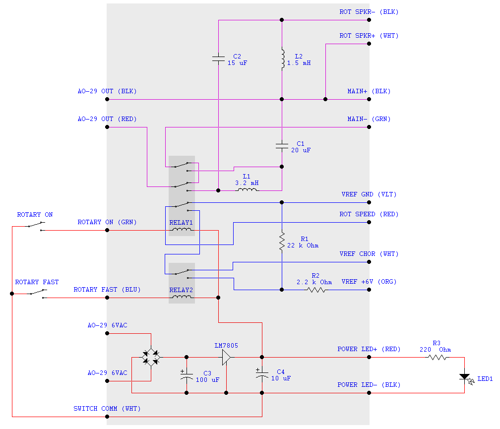
Here is wiring for that speaker :
You should go for Leslie rotary speaker IMHO ...
Get something like that on eBay :
Two Speed Leslie Tremolo Speaker
You can put driver of your choice, and there is a LOT of parts for leslie around to build nice rotary cabinets ...
This guy selling complete rotary set of original Leslie :
Leslie 120 organ speaker parts / Tremolo, motor, spindles, pulleys, Junction box
Leslie 120 organ speaker parts / Tremolo, motor, spindles, pulleys, Junction box
thanks for the reply and the wiring diagram, though can't understand it.
I have already got the speakers for this yamaha type and I'm not create a leslie which will be to big and not give the floyd tones im looking for. thanks though
I have already got the speakers for this yamaha type and I'm not create a leslie which will be to big and not give the floyd tones im looking for. thanks though
Actual answers: 6 VAC at an amp should be sufficient. This would be from a line voltage to 6 VAC transformer.• What power supply will I need to power both units from one supply?
• Will I need a stereo pot (variable resistor) to control the speed on both units at the same time.
• When I hooked up one speaker to my amp (15watt) the output level was a lot lower then the normal speaker (also 8 ohms). Any ideas why this might be?
Thanks for your help
Yes, you prevent interaction with speed pots you should buy a two element potentiometer. However most stereo potentiometers are log taper for audio, and you probably want linear taper potentiometers. Centralab used to make elements with a hole in the middle so you could put it on the shaft of another potentiometer, but that factory seems to be dead.
For low volume you need to measure the speaker resistance with an ohmmeter to make sure the coil doesn't have any shorted turns. On an 8 ohm speaker 6.5 ohms is about right. Use a 6.8 ohm resistor or your working speaker as a calibration point, DVM's are not very reliably accurate below ten ohms. Also push the speaker center in and out gently to make sure suspension is good and the coils are not scraping.
I can't believe everybody trying to sell you something else, a Leslie. komigenie's schematic diagram was quite useful. Broken leslie cases with no electronic amp go around here for about $800. The hard part to get is the rotary horn; speakers (the driver ) can usually be replaced with something else. However the mania for leslies is such, to most players absolutely nothing else would do. I use a belt driven leslie simulator myself. I've heard a couple of real leslies, vibrato, yipee, ho hum.
To converse with more passionate rotary speaker users that know more than I do (since I won't own one, they are too big and heavy for a vibrato function) get on organforum.com the leslie section about 1/3 the way down.
Last edited:
Thanks, the pot i got was this b5k one, will this do the trick?
Stereo Mixer Pot 16mm, Linear Taper Splined Dual Lin B | eBay
Stereo Mixer Pot 16mm, Linear Taper Splined Dual Lin B | eBay
i should add that both speakers are tested by me and are in full working order. It the issue appear to be with the amp i choose, I used a laney cub 15w, connected to one speaker only.
A linear pot is the correct type, whether this has enough power specification to satisfy your Yamaha control is an experiment. Your supplier doesn't specify how many watts his potentiometers are and the Yamaha schematic doesn't show a load current.
If your speakers are 6.5 ohms DC resistance and don't have suspension problems, then you could test the amp output. !5 w into 8 ohms is 10.9 Vac, that is RMS or approximately average volts on a sine wave (flute or tibia sound). You can use an analog Voltmeter to read amp output. They don't hardly sell those anymore, and my experience with DVM's on AC out is they only work on power line frequency, otherwise putting out random numbers on music. I use a transistor radio as input for speaker test, and turn it up until it sounds funny, ie the amp is clipping a little bit.
A little more power than 15 W is traditional for Leslie's, about 30 W, I don't know about the Yamaha. This is well within the capability of a LM3886 diy amp with a 50-60 v transformer. Which see over in solid state. I like the single supply version on the datasheet myself, the add on speaker protection circuits seem to be mostly smoke and mirrors, with underrated relays that might stick closed in a fault and contacts that aren't really tested as reliable on low current music. Series speaker capacitors are pretty **** reliable working or in fault mode. I like the panasonic snap in caps of 3300 uf or 4700 uf for series speaker cap, and the same can be your single rail cap. download the lm3886 datasheet from datasheetcatalog.com or TI, and get the lm3886 with the other necessary parts like perfboard, switches, fuse, resistors capacitors from mcmelectronics.com in the east or jameco.com in the west. Alliedelectronic had a special on e-core transformers with feet last I looked, the toroid ones I don't know how to mount them without scratching a winding. I package this kind of circuit in $1 steel recipe boxes, with a heat sink bolted to the back where the power IC/transistor is to waste the heat. Takes a vise in a dirty shop, a drill and a stanley carbide hacksaw to drill the round holes or saw square holes or holes over 1/2" diameter.
Good luck.
Last edited:
Hi everybody!
Digging up a very old thread I know, but I've been using the information here to get working my own yamaha rotating speaker that I pulled from a Yamaha B-5br organ, the speaker is working, and the owner of the organ said he saw it spinning while it was still in there, but I can't get it to rotate. Following what I've gathered from here and the youtube video linked in the OP, I'm powering it with a 6 VAC transformer attached to the green - and orange + and connecting the red and yellow, and red and white wires together for the different speeds but not getting any action. Does anyone here have any additional info that might help? Thanks
Digging up a very old thread I know, but I've been using the information here to get working my own yamaha rotating speaker that I pulled from a Yamaha B-5br organ, the speaker is working, and the owner of the organ said he saw it spinning while it was still in there, but I can't get it to rotate. Following what I've gathered from here and the youtube video linked in the OP, I'm powering it with a 6 VAC transformer attached to the green - and orange + and connecting the red and yellow, and red and white wires together for the different speeds but not getting any action. Does anyone here have any additional info that might help? Thanks
So do you have a schematic for the B-5br? My service support site does not include organs.
How did you determine it wants 6vAC to run the motor?
The only Yamaha spinner I have is the RA100 schematic. That motor is a JC00008, any chance yours is too? THAT motor has a run cap and three wires, plus a couple more wires for its speed sensor. It expects mains voltage.
How did you determine it wants 6vAC to run the motor?
The only Yamaha spinner I have is the RA100 schematic. That motor is a JC00008, any chance yours is too? THAT motor has a run cap and three wires, plus a couple more wires for its speed sensor. It expects mains voltage.
Thanks for the info Enzo! Unfortunately I haven't been able to find any schematics for the B-5, so I got the voltage from the schematic posted by komigenie. I suspected that maybe it needed mains power from the comments on the youtube clip, but I'm in Australia, and didn't want to jump to that conclusion and hit it with 240v! The unit may be expecting that kind of voltage though. The motor has no markings but I've taken a couple of pics just now, in case you recognise it
Attachments
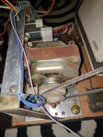
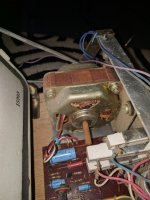
I hooked it up to the mains voltage (240v) and it works no problem, thanks Enzo. If anyone out there comes across a Yamaha organ with a rotary speaker don't hesitate to whip it out of there, great sounds, really easy to work independently of the organ. Here's what I've found:
Wires
Orange: Mains +
Green: Mains -
Red: Rotary speed common
White: Rotary speed slow
Yellow: Rotary speed fast
Purple: ground
White: Speaker +
Black: Speaker -
Put the red and white together for slow, red and yellow together for fast, I've wired them to a footswitch. The speaker is 8ohm so I'm running it out the extension output of my fender hotrod deluxe, sounds great!
- Status
- Not open for further replies.
- Home
- Live Sound
- Instruments and Amps
- Rotary Speaker Cabinet Project