TL;DR, You are probably several orders of magnitude smarter than me and i need your help to fix my old Roland amp.
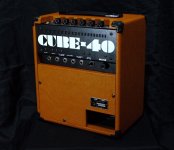
I bought a 1981 Roland Cube 40 several weeks ago as spares or repair. The amplifier is very clean cosmetically ( near mint ) but the seller said the sound would crackle and distort. I just assumed this would be dirty pots or a bad transistor at worst and didn't read too deeply in to it.
To cut a long story short, the job quickly grew arms and legs and i basically started strategically shot-gunning components that i thought might be guilty of causing the fault. As it stands ive replaced almost everything on the PCB aside from the resistors and diodes and the fault persists. I know this approach is less than ideal but my testing equipment and knowledge is severely lacking.
What is the fault?
When the guitar is strummed, a very noticeable crackle/distortion can be clearly heard among the sound of the guitar. The fault is more pronounced with bass notes and pickup output has an effect too. The amplifier has two channels, one clean and one overdrive. The overdrive channel barely does anything aside from boosting the volume slightly, i have no reference with these amps however i found someone doing a demo of one of these amps online and the overdrive channel is noticeably different when compared to my own. Worth noting that the crackle/distorted fault persists on both channels on my amp but is more prominent on the overdrive channel.
Just to rule out some suggestions people might call out, il save you some time,
Ive tried changing the guitar leads, ive tried different guitars, ive tried different plug sockets in the house, i had a brand new Fane 10" speaker that i installed, i changed the speaker wire from PCB to speaker inside the amp, i ran a solid state rackmount pre amp in to the "Main In" jack on the amp and the problem was still there. Aside from the three-core mains plug and transformer wires, ive basically re-wired the entire thing, i even made up little 3pin plug harnesses for the transistors that mount to the amp chassis. ( i did find structural corrosion on a few wires which is what prompted me to address the wiring )
Ive tried almost everything.
Important things to note,
: There was OEM security marks on all fasteners inside the amp, im quite sure that no one has touched this amplifier other than me.
: I used NOS transistors from suppliers i trust, some have modern substitutes available but i wanted to play it the way its laid out on the schematic to keep it simple.
: The unit had roughly seven carbon comp resistors, some of which had drifted drastically, ive replaced these with 1/2w carbon film so i know the values are where the schematic wants them to be.
: There is a fused resistor in the circuit which ive checked and seems to be intact with some basic continuity checks
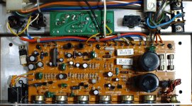
: Two wires from the transformer are providing 26vac each, go to the rectifier bridge and split to +35v and -35v, the 35v can be seen on the filtering caps and several transistors too.
: Electrolytics are all new Nichicon UFG/UFW bought from Mouser, filter caps are also Nichicon but not UFG/UFW. (cant remember which ones i used) I replaced these due to general wear and tear, some readings almost outside the acceptable tolerance. (43 years old Sanyo caps from factory)
: The performance of the amplifier has not changed in any way, shape or form after going Mach 10 with the parts cannon.
From what ive read, this is a Quasi-Complimentary design? I only do this at an entry level hobbyist stage so im not very clued up on circuit design. My background is vehicle mechanics so i trust myself to play the remove and replace game but im certainly not geared towards circuit layout and electrical engineering. I buy gear for spares or repair quite often and i usually have a high success rate but this one is beyond me. I had most of these parts already so all this has cost me so far is time.
I have a multi meter and some hopes and dreams, please help! (picture taken before work was carried out)

Attachments
Thanks for your reply, the TO-220 package is 2SD526, there are two other TO-220 packages that exist under the PCB, these are both 2SD586. If i remember correctly they aren't the transistors that appear on the schematic however those are the transistors i found when i opened the unit up so i kept them the same ( They are replaced with NOS ). With the security marks still in place i assumed that these are from factory, two of the TO-220's cant be replaced without removing the PCB and interrupting the PCB screws security marks. There was also security marks on the fasteners that attach the transistors to the amp chassis.
The TO-220 transistors are mounted the way i found them so im unsure about any further isolation, i would be open to suggestions if you have any?
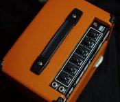
I did clean and test the jacks using some cotton buds are contact cleaner, there is certainly some tarnish/discolouration to the metal but nothing i haven't seen before. Il give it a once over again just to be sure, you think trying some 2000 grit sandpaper on the contacts would be worth a try?
Also interested to know what the relationship between the signal diodes and transistors is? Is there any chance the diodes aren't passing signal correctly, or maybe even a bias issue somehow ( if possible? )
Thanks again for your help!
Test any remaining original diodes and bipolar transistors with the diode function on your DVM. You can usually do this in-circuit.
Each PN junction should show a lowish (few hundred ohms) resistance (with red probe on the P), and open circuit (with red probe on the N).
Most bad semis will show up on this test.
Check the chassis-mounted transistors for continuity between the metal tab and the chassis. There should be none.
If do you use sandpaper on the switch contacts, use only an extremely fine grit.
Did you check the sound at the pre-out jack? If it's ok there, the problem is in the power amp section.
Thanks very much for the suggestions.
I have all of the original transistors, they were all removed without any problems so could even be re-installed if necessary, since the amp is working at the same capacity with the new transistors installed, im assuming all my new transistors fit the bill. With that said though, i don't rule out replacing bad silicon with bad silicon, i also know counterfeit parts are common and sometimes transistors can be faulty from factory so that's not lost on me.
Cleaning the jacks should be fairly easy, il just glue some sandpaper to some cotton buds and create some make-shift abrasive cleaning tools. 2000 grit is so fine you could probably wash your face with it so stray particles will be kept to a minimum. Il obviously make sure i clean it down well so i don't introduce any swarf or dust that may be conductive.
Diodes on this unit are all original and untouched by me so i can try measure those and see what's happening there, Most of the diodes on this are 1S1588 (probably Toshiba?)
Il check for continuity between the amp chassis and the transistor tab too, il need to lift the PCB to check the two 2SD586 transistors which is a pain, the PCB is very tightly packed in the chassis and its a day out just to remove the thing...
Edit: I forgot to add, i didn't check the pre amp output from the Roland on its own since i currently don't have another amp with a "Main In" that i can use. I used a Marshall 9004 solid state pre amp in to the Roland main input and the fault still occurs, When i run the Marshall pre amp in to the Roland, the only control knobs that work on the Roland are the volume knobs, everything else becomes controllable through the Marshall pre amp control knobs.
Last edited:
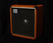
Ive added some extra pictures of the amp so everyone knows exactly what were working with here. Its almost museum worthy from an aesthetic standpoint, hard to believe its 43 years old.
Something else trivial worth noting, the fuse on the rear panel is also security marked in the same way the fasteners are, which to me, suggests that its never had any sinister faults in the past as the fuse has lasted 43 years.


Something else trivial worth noting, the fuse on the rear panel is also security marked in the same way the fasteners are, which to me, suggests that its never had any sinister faults in the past as the fuse has lasted 43 years.


"i basically started strategically shot-gunning components that i thought might be guilty of causing the fault. As it stands ive replaced almost everything on the PCB"
Not a very clever strategy I must say.
You used different sources (guitars cables) that's ok to start with.
Then you used a different speaker. It's ok...
Then you used a Marshall 9004 solid state pre amp in to the main input and the fault still occurs.
What happens if you insert a cable into the main in en short it to ground?
To be sure it's in the power amp section or the power supply, You should check the preamp out. You can send it in to the Marshall.
If that's ok, the problem is in the power amp section.
Possibly in the power supply that feeds the power amp.
Can you take some measurements (voltage)? Give them...
And stop with changing parts without knowing if they are bad.
Even if you use the same parts...
First find out where the problem resides. Not allways easy.
To recapitulate:
A combo has 4 parts.
1. Power supply
2. Preamp
3. Power amp
4. Speaker
Check each first and then proceed deeper in the unit.
Success.
- Home
- Live Sound
- Instruments and Amps
- Roland Cube 40 distorted output