Hi my friend has a roland 909 and it needs a new 7 segment LED .
Can anyone help me work out how to find a way to use modern ones or are there NOS places.
Thanks
Can anyone help me work out how to find a way to use modern ones or are there NOS places.
Thanks

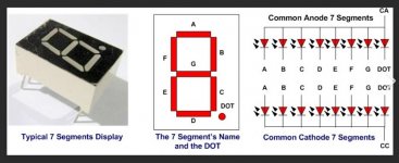
As a generalisation you first need to actually look and see what is fitted meaning are these normal individual 7 segment displays or is it some more complex module. Look carefully for any identifying markings and numbers as these can help.
If they are normal 7 segment types then you next need to identify whether they are common cathode or common anode which can be done with meter on diode range (it should light each segment as tested).
Then its a case of seeing what is available in a suitable size and correct pin out.
Edit... looks like we posted together.
Attachments
Mooly I guess they are not standardised for pin out,I am new to 7 segment displays
And do they work at different voltages?
thanks
And do they work at different voltages?
thanks
Last edited:
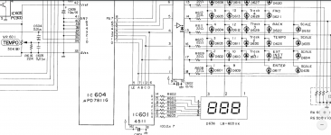
On your thumbnail is the part number, so I looked it up, Rohm made it. U can't grab teh data sheet address, so here is the page, click on the data sheet button.
Three Digit LED Numeric Displays - LB-603VF | ROHM Semiconductor - ROHM Co., Ltd.
Three Digit LED Numeric Displays - LB-603VF | ROHM Semiconductor - ROHM Co., Ltd.
Good question. You would need to check by putting the red lead of the meter (on diode range) on the common pin for one of the displays (pin 1, 2 or 3) and with the black lead touch the other pins and see if all the segments light in turn. If they do its common anode.
If they don't then swap the leads over. If they light with black on one of those three pins (1, 2 or 3) then it is common cathode.
Voltage should be pretty standard (just normal red LED voltage) and the current is limited by those seven 100 ohm resistors.
I think the first thing to do is actually get the display in front of you so you can test it properly. There are plenty of references to LB603 displays but not that exact suffix and the ones I can see look very different.
https://docs.rs-online.com/fd21/0900766b81539a21.pdf
- Home
- Live Sound
- Instruments and Amps
- Roland 909 7 segment repacement